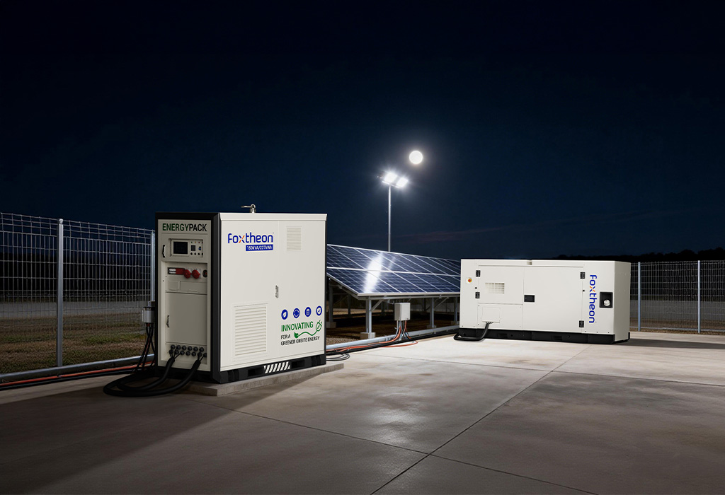
For industrial facilities, the integration of battery storage into a microgrid goes beyond simple backup. A properly engineered microgrid BESS (Battery Energy Storage System) improves renewable self-consumption, reduces peak demand, and provides seamless islanding. This article examines seven technical layers—from cell selection to grid-forming inverters and supervisory control—that determine real-world performance in manufacturing plants, data centers, and remote industrial sites.
1. Battery Chemistry Selection for Cyclic and Standby Duty
Industrial microgrid BESS applications fall into two duty profiles: daily cycling (peak shaving, load shifting) and emergency standby (backup, black start). Lithium iron phosphate (LFP) dominates cycling applications due to 6,000+ cycles at 80% depth of discharge and lower thermal runaway risk. For standby-heavy installations with fewer than 200 cycles per year, nickel manganese cobalt (NMC) or even advanced lead-carbon can be cost-effective, but requires stricter thermal management. The battery management system (BMS) must track coulombic efficiency and internal resistance trends to predict end-of-life, enabling predictive replacement planning.
Cell Balancing and String Topology
Parallel strings introduce circulating currents if state-of-charge (SoC) diverges. Active balancing circuits (capacitive or transformer-based) redistribute energy between cells, achieving string-level SoC mismatch below 2%. For high-voltage DC buses (800–1500 V), modular multilevel converter (MMC) topologies allow per-module SoC control, reducing the need for external balancing.
2. Power Conversion System (PCS) – Grid-Following vs. Grid-Forming
The inverter is the interface between the battery and the microgrid bus. Traditional PCS operates in grid-following mode, relying on an external voltage reference. However, for weak grids or islanded microgrids, a microgrid BESS must support grid-forming mode, where the inverter establishes voltage and frequency. Key parameters:
- Grid-following: Fast current control, suitable for peak shaving and frequency response (droop curves). Requires a stiff grid or a grid-forming source elsewhere.
- Grid-forming: Voltage source behavior with virtual inertia emulation. Enables black start and seamless transition between on-grid and off-grid.
- Transition time: Industrial standards require islanding detection within 100 ms and reconnection within 5 minutes after grid restoration.
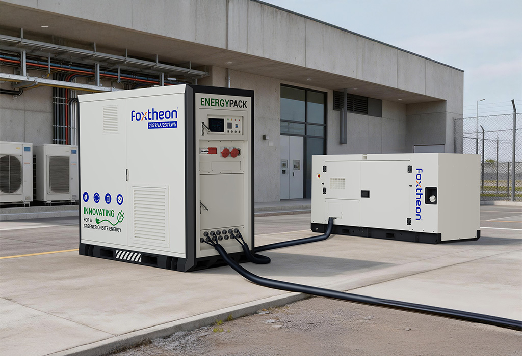
Modern PCS units from suppliers like Foxtheon integrate both algorithms, automatically switching based on measured grid impedance and breaker status.
3. Microgrid Controller Hierarchy – From Local to Supervisory
A microgrid BESS relies on a three-layer control architecture: primary (local, millisecond response), secondary (seconds to minutes, voltage/frequency restoration), and tertiary (economic dispatch, coordinated with utility prices).
Primary Control
Implemented within the PCS or a dedicated fast PLC. Functions include droop control (P-f and Q-V), virtual synchronous machine (VSM) algorithms, and fault current limitation. Response time ≤20 ms.
Secondary Control
Restores voltage and frequency to nominal after load or generation changes. Often uses a central microgrid controller communicating via IEC 61850 GOOSE messages. This layer also manages state-of-charge (SoC) balancing among multiple battery racks.
Tertiary Control
Optimizes battery dispatch based on time-of-use tariffs, weather forecasts (for solar/wind), and generator fuel prices. Machine learning models predict 24-hour load profiles; the controller then schedules charge/discharge cycles to maximize operational savings without exceeding battery cycle budgets.
4. Protection Coordination with Battery Fault Contributions
Adding a microgrid BESS alters short-circuit current levels. While inverters typically contribute 1.2–1.5× rated current for a few cycles (unlike synchronous generators with 5–10×), protection devices must be re-evaluated. Three common adjustments:
- Directional overcurrent relays (67): Needed at the point of common coupling (PCC) to distinguish between upstream faults and downstream microgrid faults.
- Voltage-restrained overcurrent (51V): Prevents nuisance tripping during weak grid conditions where fault current is low.
- Reverse power relay (32): Detects unintentional backfeed into the utility. Must be coordinated with intentional reverse power from the BESS during peak shaving.
A protection study using software like ETAP or EasyPower is mandatory before commissioning. The study should simulate both grid-connected and island modes, as fault levels differ by an order of magnitude.
5. Key Application Scenarios for Industrial Microgrid BESS
Engineering decisions vary by use case. Below are three high-value industrial deployments with specific technical requirements.
Manufacturing Plants with High Motor Starting Loads
Large induction motors (e.g., compressors, shredders) draw 6–8× rated current during start. A microgrid BESS can supply this starting current without voltage sag, allowing the rest of the plant to continue operation. The BESS must support short-term overload (150% for 10 seconds) and fast recharging after start. Inverter thermal design should accommodate repetitive overloads.
Remote Mining and Processing Facilities
Sites powered by diesel gensets suffer from low efficiency at partial load. A battery system enables genset optimization: gensets run at 70–85% load (their optimal brake specific fuel consumption), and the battery charges/discharges to absorb load variations. This reduces fuel consumption by 25–30% without replacing existing generators. The microgrid BESS controller must respect genset start/stop limits (typically 2–3 starts per hour) and minimum run times.
Data Center and Critical Infrastructure
While UPS systems provide seconds to minutes of ride-through, a microgrid BESS extends runtime to hours when paired with backup generators. More importantly, it improves power quality by actively filtering harmonics (up to 25th order) and compensating for voltage sags from utility faults. Tier-IV facilities often deploy dual-bus microgrids with redundant battery strings, each with independent BMS and fire suppression.
6. Addressing Industry Pain Points with Intelligent BESS Control
Engineers frequently raise concerns about battery degradation, control stability during islanding, and renewable intermittency. A well-specified microgrid BESS resolves these through algorithmic measures.
Pain Point: Battery Cycle Life in Daily Peak Shaving
Solution: Adaptive state-of-charge (SoC) windows. Instead of cycling between 10% and 100%, the controller narrows the window to 30–80% on weekdays (reducing depth of discharge) and widens to 15–90% only during grid emergencies. Additionally, partial state-of-charge (PSOC) operation with periodic full charges prevents capacity drift. Thermal preconditioning (heating or cooling the battery before heavy cycles) further slows calendar aging.
Pain Point: Instability When Switching to Island Mode
Solution: Seamless transition requires a static transfer switch (STS) or a fast-acting microgrid breaker with <50 ms opening time. The BESS inverter must support phase-locked loop (PLL) with a fast re-latching mechanism. Pre-islanding load shedding is often necessary: non-critical loads are disconnected first, then the battery assumes grid-forming control. This sequence is automated by the microgrid controller and tested via hardware-in-the-loop (HIL) simulation.
Pain Point: Integration with Existing Generator Fleets
Solution: Retrofit controllers like those from Foxtheon communicate via CAN J1939, Modbus, or hardwired analog signals. They read generator load, frequency, and alarm status, then adjust battery power to keep generators within their optimal band. No generator replacement is required; the existing AVR and governor remain primary controls.

7. Commissioning and Testing Protocols for Microgrid BESS
A reliable microgrid BESS requires site-specific acceptance tests. Minimum test sequence:
- Grid-connected tests: Verify power ramp rates, reactive power capability (typically ±0.9 PF), and harmonic compliance (IEEE 519). Perform 30-minute steady-state runs at 25%, 50%, 75%, and 100% rated power.
- Transition tests: Simulate utility loss using an upstream breaker. Measure transfer time (≤100 ms for critical loads). Repeat at different battery SoC levels.
- Black start test: Isolate microgrid from utility, discharge battery to 5% SoC, then initiate black start sequence. Verify that the battery energizes the microgrid bus and that generators synchronize within 5 minutes.
- Protection coordination test: Inject secondary fault currents to verify directional relay settings and breaker trip times. Document time-current curves.
Commissioning engineers should also validate the fire suppression system (NFPA 855 compliant) and remote monitoring connectivity (e.g., cellular or fiber to cloud SCADA).
Frequently Asked Questions (FAQ)
Q1: Can a microgrid BESS operate in parallel with existing diesel generators without modifying the generator’s internal controls?
A1: Yes. Using a retrofitted microgrid controller that reads the generator’s load via current transformers or the generator’s CAN bus, the BESS can absorb or supply power as needed. The generator’s voltage regulator and governor remain unchanged; they see the BESS as a variable load or source. This approach preserves generator warranties and service contracts.
Q2: What communication protocols are standard for integrating a microgrid BESS with site SCADA or building management systems?
A2: Most industrial systems support Modbus TCP/IP (RTU), IEC 61850 MMS/GOOSE, DNP3, and OPC UA. For simpler installations, dry contact relays and 4–20 mA analog signals are still common. The microgrid controller acts as a gateway, translating between battery BMS/PCS protocols (often CAN or proprietary) and the site’s preferred standard.
Q3: How does a microgrid BESS handle unbalanced loads (e.g., single-phase lighting mixed with three-phase motors)?
A3: Three-phase PCS with per-phase independent current control can compensate for imbalances up to 100% of the phase rating. The controller monitors negative-sequence voltage and injects opposing currents. For severe imbalances, a delta-wye transformer on the battery output can provide additional zero-sequence blocking. This is particularly relevant for commercial buildings with mixed loads.
Q4: What are the key regulatory approvals required for installing a microgrid BESS in industrial zones?
A4: In North America, UL 9540 (system listing) and UL 9540A (thermal runaway propagation test) are mandatory. NFPA 855 limits capacity per smoke zone and requires spacing or fire barriers. The interconnection agreement with the utility (e.g., IEEE 1547-2018) may require anti-islanding and power quality tests. In the EU, IEC 62619, IEC 62477, and grid codes like VDE-AR-N 4105 apply. Always involve a licensed professional engineer for local amendments.
Q5: How do you manage battery state-of-charge (SoC) uncertainty during extended islanded operation?
A5: A hybrid approach: use high-accuracy coulomb counting with periodic voltage-based recalibration. During islanding, the BMS performs a “rest recalibration” if the battery is idle for >30 minutes. Additionally, the microgrid controller reserves 10–15% of battery capacity as a hidden buffer for emergency black start. Load shedding algorithms prioritize critical loads when SoC falls below 20%.
Q6: What is the typical response time for a microgrid BESS to switch from peak shaving to islanding mode?
A6: With a fast static transfer switch and a grid-forming inverter, the total transition time (utility loss detection → breaker open → inverter voltage established) is 30–80 milliseconds. Sensitive equipment such as variable frequency drives and PLCs will continue operation without interruption. Standard transfer switches (electromechanical) take 100–200 ms, which may cause contactor dropout; thus STS is recommended for critical loads.
Need to engineer a microgrid BESS for your industrial facility? Foxtheon provides feasibility studies, protection coordination, and turnkey commissioning. Fill out the inquiry form below to receive a preliminary technical assessment and a system sizing proposal based on your load profiles and existing assets.
→ Submit an Inquiry (Request for Technical Proposal) — Our application engineers will respond within 48 hours with a detailed data collection checklist and a follow-up call to discuss your microgrid requirements.