Commercial and industrial (C&I) facilities face complex challenges in maintaining power stability, managing peak demand charges, and integrating variable renewable generation. To resolve these challenges, engineers must focus on high-performance energy buffer systems. Integrating a robust battery energy power subsystem provides the rapid response necessary to stabilize local distribution networks. This approach allows facilities to maintain operational continuity without abandoning existing generation infrastructure. Experienced manufacturers like Foxtheon design modular, highly configurable storage solutions that bridge the gap between traditional electrical assets and modern, localized smart grids.
1. Electrochemical Selection and Structural Protection
Selecting the appropriate battery chemistry is the first step in engineering a stable stationary storage system. While various chemistries exist, Lithium Iron Phosphate (LFP) and Nickel Manganese Cobalt (NMC) dominate industrial applications. For stationary C&I microgrids, LFP is widely preferred due to its specific performance characteristics:
- Thermal Stability: LFP cells exhibit a high thermal runaway threshold (typically around 270°C) compared to NMC cells (approximately 210°C), reducing risks associated with internal short circuits or overheating.
- Cycle Longevity: LFP systems routinely deliver between 5,000 and 8,000 cycles at an 80% Depth of Discharge (DoD), ensuring long-term operational viability.
- Voltage Plateaus: LFP maintains a stable nominal voltage of 3.2V throughout most of its discharge curve, which simplifies power conversion and module balancing.
Beyond internal electrochemistry, the mechanical housing must protect the sensitive cells from environmental hazards. Heavy-duty enclosures constructed from hot-dip galvanized steel or marine-grade aluminum are necessary. In coastal or highly humid environments, these structures must meet C4 or C5 corrosion resistance ratings. To prevent moisture ingress, enclosures require at least an IP54 or IP55 ingress protection rating. This ensures that the internal thermal behavior of the battery energy power storage cells remains unaffected by external dust, rain, or humidity fluctuations.
2. Control Architectures: BMS, PCS, and EMS Integration
A functional energy storage system relies on a three-tier control architecture to translate raw electrochemical potential into usable alternating current (AC). The system relies on three primary components: the Battery Management System (BMS), the Power Conversion System (PCS), and the Energy Management System (EMS).
The Battery Management System (BMS)
The BMS operates on a hierarchical topology. At the lowest level, Battery Module Units (BMUs) monitor individual cell voltages and temperatures. These units report to a central Rack Battery Management System (RBMS), which aggregates data and controls contactors. At the system level, the master BMS coordinates multiple racks, balancing the state of charge (SoC) across parallel strings and executing safety disconnect protocols when current, voltage, or thermal limits are exceeded.
The Power Conversion System (PCS)
The PCS acts as the bi-directional gateway between the DC battery bank and the AC utility grid or local microgrid. Utilizing high-efficiency insulated-gate bipolar transistors (IGBTs) or Silicon Carbide (SiC) metal-oxide-semiconductor field-effect transistors (MOSFETs), the PCS manages both active and reactive power flow. It must support grid-following modes (locking onto utility voltage and frequency using phase-locked loops) and grid-forming modes (creating an independent voltage source during grid outages).
The Energy Management System (EMS)
The EMS serves as the overarching intelligence of the facility. It analyzes external signals—such as real-time electricity pricing, weather forecasts, and building load demand—and determines when the core battery energy power block interacts directly with local energy assets. This coordination ensures that power import limits are never exceeded, reducing peak demand fees.
3. Thermal Management Dynamics: Liquid vs. Air Cooling
Thermal control is a key factor in preventing degradation and ensuring safety. When cells operate outside their optimal window (typically 15°C to 35°C), internal resistance increases, capacity fades, and the likelihood of localized hot spots rises. System designers choose between two primary cooling technologies:
| Parameters | Forced-Air Cooling Systems | Direct Liquid Cooling Systems |
|---|---|---|
| Temperature Uniformity | ±3°C to ±5°C across the rack | ±1°C to ±2°C across the rack |
| Parasitic Power Draw | Moderate (high fan speeds required under load) | Low (efficient pump operation) |
| System Footprint | Larger due to required airflow channels | Compact, maximizing volumetric energy density |
| Maintenance Profile | Simple filter replacements | Periodic coolant level and hose inspections |
Liquid cooling systems utilize a closed-loop design with a glycol-water mixture pumped through cooling plates in direct contact with the cells. This method provides highly uniform temperature distribution, which prevents uneven aging among cells in series. Maintaining a uniform thermal profile reduces maintenance needs and ensures predictable performance throughout the system’s operational lifespan.
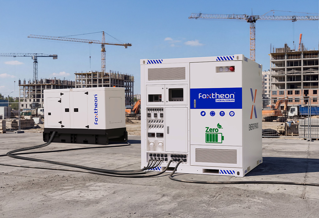
4. Optimizing Hybrid Microgrids and Supporting Existing Generator Assets
Industrial facilities often rely on on-site diesel or natural gas generators to provide reliable backup power. However, running generators at low loads during off-peak periods causes wet stacking, carbon build-up, and poor fuel efficiency. Integrating energy storage resolves these operational issues.
Instead of running generators continuously at low load factors, the system can operate them at their optimal fuel curves. Utilizing battery energy power to absorb transient loads and provide rapid spinning reserve capacity allows generators to shut down or run only when needed. This hybrid configuration improves overall fuel efficiency and extends the physical lifespan of the generator assets by reducing wear and tear. During transient load spikes, the battery system reacts within milliseconds to inject active power, preventing voltage sags that could trip sensitive industrial equipment.
5. Sourcing Criteria and Supplier Evaluation Standards
Selecting the right hardware partner is a critical phase in system integration. Engineering procurement contracts (EPCs) must look beyond simple upfront acquisition costs and evaluate technical design standards, certifications, and manufacturing practices. Key engineering requirements include:
- Certifications: Verify compliance with global safety standards, such as UL 1973 (for batteries in stationary applications), UL 9540A (to evaluate thermal runaway fire propagation), and IEC 62619 (for industrial safety requirements).
- Round-Trip Efficiency (RTE): Specify an AC-to-AC RTE of at least 85% to 88% to minimize losses during charge and discharge cycles.
- Structural Rigidity: Ensure the containerized solutions meet local seismic and wind-load standards.
When evaluating commercial battery energy power hardware, procurement teams benefit from working with vertically integrated providers. Integrated systems, such as those engineered by Foxtheon, provide pre-tested, factory-configured matches between the battery racks, BMS, and liquid-cooling chillers. The engineering standards followed by Foxtheon emphasize high volumetric energy density and robust structural vibration resistance, reducing installation time and integration complications at the project site.
6. Technical Frequently Asked Questions
Q1: Why is Lithium Iron Phosphate (LFP) preferred over Nickel Manganese Cobalt (NMC) for stationary industrial storage applications?
A1: LFP is preferred primarily for safety and longevity. LFP has a higher thermal runaway temperature threshold and does not release oxygen during thermal breakdown, significantly reducing fire risk. Additionally, LFP supports up to twice the cycle life of NMC, making it more suitable for daily cycling applications over a 10-to-15-year operational window.
Q2: How does a battery energy power system maintain stability in a hybrid microgrid?
A2: The system utilizes advanced grid-forming inverters that operate in a virtual synchronous machine mode. These inverters monitor grid frequency and voltage deviations, instantly injecting or absorbing active and reactive power within milliseconds to compensate for load transients or renewable energy output fluctuations.
Q3: What role does UL 9540A testing play in commercial energy storage deployment?
A3: UL 9540A is a rigorous test standard that evaluates thermal runaway fire propagation. It tests cells, modules, and racks to determine if a thermal runaway event in one cell will propagate to neighboring cells. Achieving successful UL 9540A test results is a key requirement for securing permits from local authorities having jurisdiction (AHJs) and ensuring facility safety.
Q4: How does liquid cooling improve battery performance compared to forced-air cooling?
A4: Liquid cooling has a heat transfer coefficient up to ten times higher than air. This allows the system to maintain a temperature variation of less than ±2°C across all cells in a rack. Uniform temperatures prevent localized cell degradation, minimize parasitic power consumption from cooling fans, and allow the system to operate reliably in high ambient temperatures.
Q5: What are the main integration challenges when connecting energy storage to existing generator systems?
A5: The primary challenges are communication latency and load sharing. To ensure smooth transitions, the Energy Management System (EMS) must communicate with both the generator controller and the storage system’s PCS using fast protocols like Modbus TCP or CAN bus. This fast communication ensures the battery can absorb load spikes instantly while the generator ramps up its output at a stable rate.
Inquiry
For detailed engineering specifications, single-line diagrams, or customized system configurations tailored to your facility’s operational profile, please contact our technical application team.