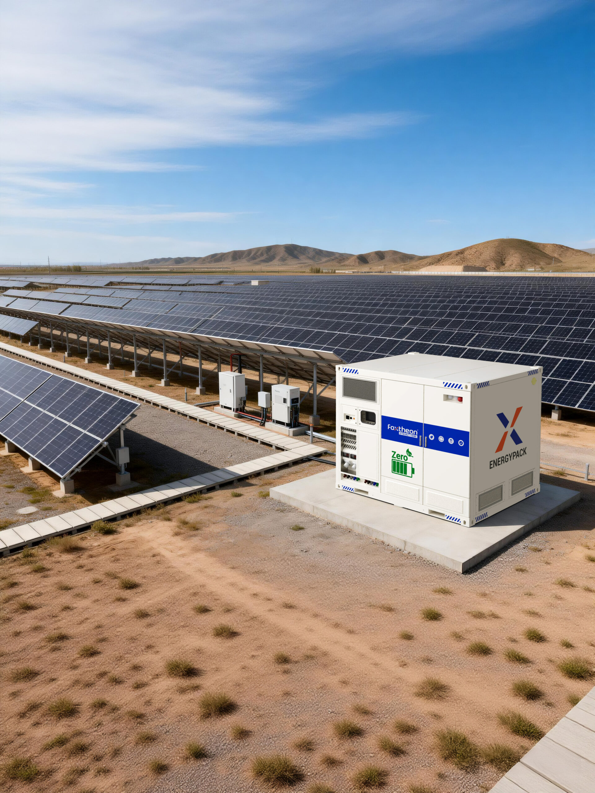
Modern industrial facilities face mounting pressure to maintain power quality and grid stability amid rising electricity demands and localized infrastructure constraints. Grid congestion, voltage fluctuations, and strict peak-demand tariffs necessitate localized, high-capacity energy storage solutions. For many engineering and facilities management teams, the deployment of a commercial utility-scale system offers a reliable mechanism to manage load profiles, provide peak shaving, and secure backup power reserves.
Integrating a bess battery storage system into an existing electrical network requires a comprehensive understanding of battery chemistry, thermal dynamics, system architecture, and control interfaces. Standardized solutions developed by manufacturers like Foxtheon provide the necessary technological foundation to stabilize local networks while working in harmony with pre-existing energy assets.
1. Electrochemical Cell Selection: LFP vs. NMC
The choice of battery chemistry dictates the operating parameters, lifetime safety, and performance boundaries of any large-scale storage installation. Commercial and Industrial (C&I) deployments predominantly utilize two lithium-ion variants: Lithium Iron Phosphate (LFP) and Nickel Manganese Cobalt Oxide (NMC). Evaluating these chemistries involves analyzing their thermodynamic properties and cycle degradation characteristics.
Lithium Iron Phosphate (LFP)
LFP chemistry has become the preferred standard for stationary energy storage applications. The primary technical advantages include:
- Thermal Safety: LFP cells exhibit a high thermal runaway threshold (approximately 270°C) and do not release oxygen during structural decomposition, significantly reducing fire propagation risks.
- Cycle Life: LFP cells typically deliver between 5,000 and 8,000 cycles at an 80% Depth of Discharge (DoD) before capacity degrades to 80% of its nominal value.
- Structural Integrity: The olivine crystal structure of LFP undergoes minimal volume expansion during charge and discharge cycles, preserving physical cell integrity over prolonged operating periods.
Nickel Manganese Cobalt (NMC)
While NMC chemistry offers superior gravimetric and volumetric energy density, its application in stationary systems is constrained by specific operational trade-offs:
- Thermal Sensitivities: NMC has a lower thermal runaway threshold (around 210°C) and is prone to self-sustaining exothermic reactions under extreme thermal fault conditions.
- Degradation Rates: NMC chemistries generally exhibit a lower cycle life (typically 2,000 to 4,000 cycles) under similar discharge rates, making them less suitable for high-frequency cycling applications like daily peak shaving.
2. Structural Enclosure Design and Panel Materials
The physical housing of a bess battery storage system must withstand environmental hazards, maintain precise internal temperatures, and contain internal thermal events. The structural integrity of containerized systems relies heavily on advanced material science and double-walled panel configurations.
Enclosure Panel Materials and Insulation
The exterior walls of containerized storage systems are typically fabricated from structural carbon steel sheets or marine-grade aluminum, treated with high-durability anti-corrosion coatings rated for C4 or C5 corrosive environments. Between the outer and inner metal sheets, high-density non-combustible insulation is integrated:
- Rockwool / Mineral Wool Insulation: Class A1 non-combustible mineral wool is standard for insulation cores, offering superior fire barrier properties (up to 120 minutes of thermal isolation) and structural stability.
- Polyurethane (PU) Foam Panels: Used primarily in highly controlled environments, PU panels offer excellent thermal conductivity ratings (R-values) to minimize HVAC energy consumption, though they require additional fire-retardant additives to meet strict safety codes.
Thermal Management Systems
Maintaining temperature uniformity across thousands of individual cells is vital to prevent localized cell degradation. Thermal management architectures are categorized into two primary methods:
- Liquid Cooling: Liquid-cooled plates containing a mixture of water and ethylene glycol are placed in direct thermal contact with the cells. This configuration yields superior temperature uniformity, keeping cell temperature deviation (ΔT) within ±2°C, which directly extends overall system life. Integrated systems from Foxtheon feature multi-tiered protection mechanisms to isolate fluid pathways from high-voltage electrical architecture.
- Forced-Air Cooling: Air-cooled designs rely on high-capacity HVAC units and ducting networks to distribute chilled air throughout the container. While mechanically simpler, air cooling typically results in higher ΔT profiles across large battery racks, particularly during high C-rate charge and discharge cycles.
3. Control Interfaces: BMS, EMS, and PCS Interoperability
The operational efficiency of a bess battery storage installation is governed by the seamless interaction of three distinct control layers: the Battery Management System (BMS), the Power Conversion System (PCS), and the Energy Management System (EMS).
The Three-Tier Battery Management System (BMS)
The BMS operates at the lowest latency level to protect the cells from electrical and thermal abuse. The architecture is organized hierarchically:
- Local Monitoring Unit (LMU): Measures individual cell voltages and surface temperatures directly at the module level.
- Pack Management Unit (PMU): Collects data from multiple LMUs, manages cell balancing (passive or active), and monitors string current.
- System Management Unit (SMU): Interfaces with external controllers, manages the master high-voltage contactors, and calculates state-of-charge (SoC) and state-of-health (SoH) metrics.
Power Conversion and Grid Synchronization
The PCS acts as the bidirectional gateway between the DC battery array and the AC grid network. Achieving rapid response times (under 50 milliseconds) for frequency regulation and voltage support requires high-speed digital signal processors (DSPs) and reliable communication protocols, such as Modbus TCP/IP, CAN bus, or IEC 61850. The PCS must manage dynamic reactive power injection (VAR support) and ride-through grid disturbances without disconnecting from the network.
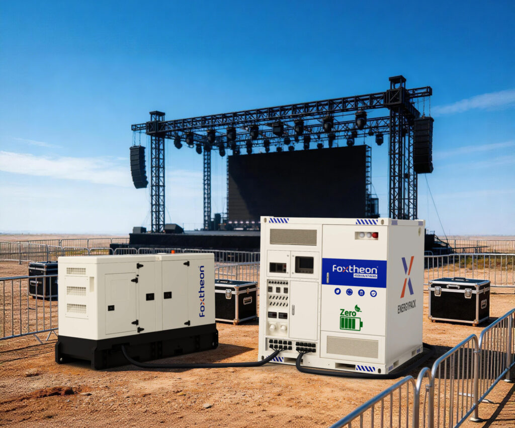
4. Co-Existence and Integration with Existing Generator Assets
A primary objective for many industrial facilities is optimizing the operation of existing thermal generation systems, such as diesel or natural gas generator sets. Incorporating a bess battery storage system does not mean replacing these assets; rather, it allows them to operate under optimized conditions.
Thermal generators operate most efficiently within a specific load window—typically between 70% and 90% of their rated capacity. When subjected to highly variable load steps or run at low load factors, generators suffer from incomplete combustion, increased soot buildup (known as wet stacking), and accelerated mechanical wear. By utilizing energy storage as a dynamic buffer:
- Load Levelling: The battery system absorbs transient load spikes and discharges to support the generator during peak demands, ensuring the thermal unit remains within its optimal efficiency zone.
- Spinning Reserve: The battery provides immediate power during a grid outage, granting generator assets the necessary start-up and synchronization window (typically 10 to 15 seconds) without causing localized brownouts or voltage drops.
5. Sourcing, Specifications, and Technical Evaluation
Procuring a utility-grade battery storage system requires a meticulous review of vendor datasheets, compliance documentation, and performance curves. Engineers should prioritize several critical parameters during the technical evaluation process:
| Technical Parameter | Standard Commercial Range | Engineering Significance |
|---|---|---|
| C-Rate (Charge/Discharge) | 0.5C to 1.0C | Determines how quickly the system can be fully charged or discharged relative to its total capacity. |
| Round-Trip Efficiency (RTE) | 85% to 92% | Measures energy lost as heat during the charge-discharge loop, directly affecting operational efficiency. |
| Auxiliary Power Load | < 5% of rated power | The energy consumed by HVAC, BMS, and controller systems; lower values preserve usable capacity. |
| Safety Certifications | UL 9540, UL 1973, IEC 62619 | Ensures compliance with global safety standards for cell, module, and system-level thermal runaway mitigation. |
To ensure high performance across diverse operating conditions, modern platforms like Foxtheon facilitate seamless data logging and remote diagnostics. This allows asset managers to monitor battery health metrics and optimize discharge profiles in real time, preventing premature degradation.
Frequently Asked Questions
Q1: What is the expected operational lifespan of a commercial bess battery storage system?
A1: Under typical operational parameters (1-2 cycles per day, 80% Depth of Discharge, and temperature-controlled environments), high-quality LFP chemistry systems are engineered to last between 10 and 15 years before the nominal capacity drops to 80% of its initial value.
Q2: How does thermal management affect safety in containerized systems?
A2: Proper thermal management prevents localized hot spots that can trigger thermal runaway. Liquid cooling systems maintain tight temperature uniformity across all cells, keeping deviations minimal, which mitigates the risk of cell degradation and catastrophic thermal events.
Q3: Can a commercial battery system operate in extreme environmental conditions?
A3: Yes. Enclosures rated with IP55 or IP65 ingress protection, combined with double-walled insulated panels and industrial HVAC units, allow energy storage systems to operate reliably in ambient temperatures ranging from -20°C to 50°C.
Q4: How do control protocols like Modbus and IEC 61850 impact system integration?
A4: These standardized communication protocols enable high-speed, low-latency data exchange between the BMS, PCS, EMS, and factory automation networks. This seamless integration ensures the energy storage system can respond to grid frequency changes or external commands in milliseconds.
Q5: Why is LFP preferred over NMC for stationary energy storage?
A5: LFP offers superior safety due to its higher thermal runaway temperature, a significantly longer cycle life (double that of NMC), and better structural stability. While NMC is highly energetic, LFP is better suited for stationary systems where weight is not a primary constraint.
Submit an Inquiry for Your Project
For detailed engineering specifications, customized system sizing, or integration support with existing industrial equipment, please submit your technical requirements. Our application engineering team will review your parameters and provide a comprehensive system proposal.