
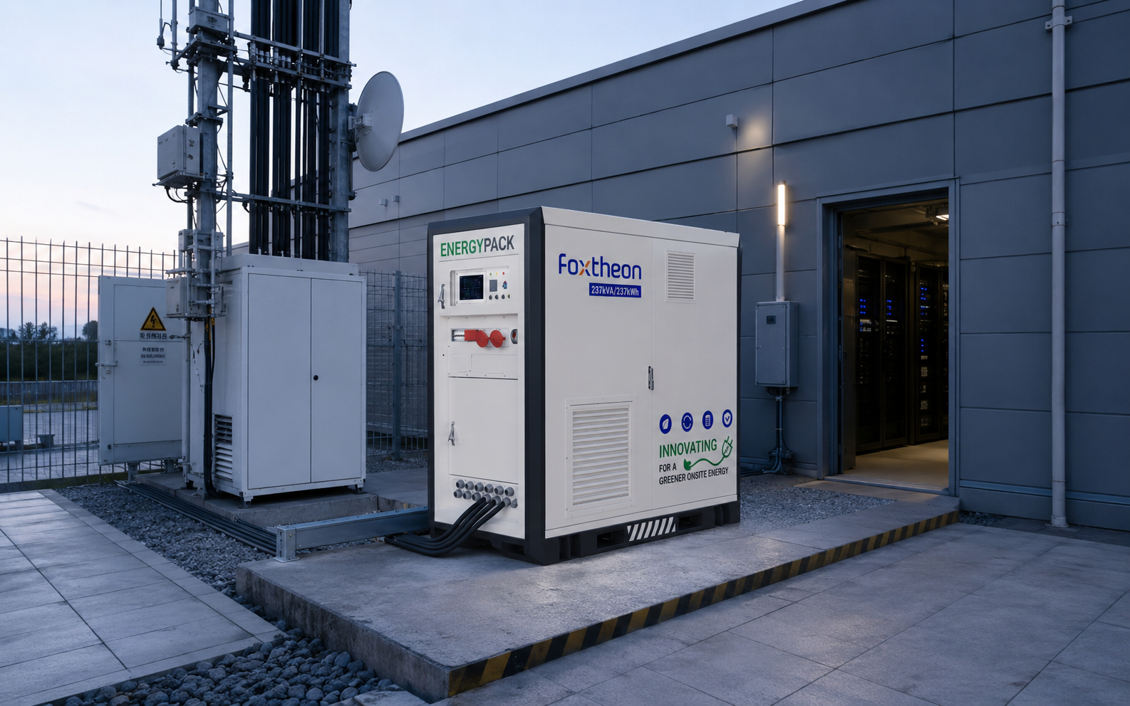
Modern decentralized energy systems increasingly demand the integration of multiple generation sources to supply continuous, high-quality electricity to demanding industrial loads. Industrial facilities operating in off-grid, weak-grid, or edge-of-grid environments traditionally depend on reciprocating internal combustion engines. While these thermal assets provide dependable baseline energy and high fault-clearing capabilities, running them continuously across variable load profiles leads to sub-optimal loading conditions, such as engine wet stacking and high fuel burn rates. Integrating continuous renewable generation and fast-responding battery storage alongside existing reciprocating engines forms an advanced hybrid power architecture. This engineering approach stabilizes operational dynamics without discarding or devaluing existing mechanical infrastructure.
Rather than discarding traditional mechanical assets, an engineered hybrid power microgrid treats existing generator sets as complementary generation resources within an expanded, multi-asset generation matrix. The objective is to achieve electrical equilibrium: balancing fluctuating load profiles with intermittent solar photovoltaic (PV) generation, maintaining precise system voltage and frequency, and running mechanical engines strictly within their sweet spot on the brake-specific fuel consumption (BSFC) curve.
Topological Design: AC-Coupled vs. DC-Coupled Synchronization
The layout of a multi-source microgrid depends on the coupling point of the renewable energy generation, energy storage systems (BESS), and reciprocating generation assets. Engineers must choose between AC-coupled and DC-coupled architectures based on scale, cable distances, and load dynamics.
AC-Coupled Microgrid Topologies
AC-coupled topologies connect all generation assets—including solar PV inverters, battery power conversion systems (PCS), and synchronous generators—to a centralized alternating current busbar (typically 400V, 480V, or medium-voltage levels such as 11kV or 33kV). This configuration suits geographically dispersed systems or retrofit projects where a generator station is already installed.
- Design Flexibility: Solar arrays, battery enclosures, and diesel or gas gensets can sit hundreds of meters apart, communicating through optical fiber fieldbuses while injecting power directly into the local distribution board.
- Redundancy: The failure of a single solar inverter or battery rack does not bring down the balance of the AC bus, allowing the remaining thermal or electrochemical sources to continue servicing the facility load.
- Complex Control Schemes: Balancing an AC bus requires responsive control algorithms. Fast changes in solar irradiance can cause reverse power flows toward the generator busbar, requiring millisecond-level curtailment or storage absorption to protect thermal engine reverse-power relays (ANSI 32).
DC-Coupled Microgrid Topologies
In DC-coupled architectures, solar PV arrays and electrochemical energy storage systems converge on a shared direct-current bus via DC-DC buck or boost converters before feeding a common, bidirectional inverter. Thermal generators interface downline on the AC side via standard synchronization switchgear.
- Conversion Efficiency: Solar power charges the battery bank directly through high-efficiency MPPT DC-DC stages, avoiding double-conversion losses (DC to AC, then AC back to DC).
- Centralized Inverter Stress: The main central inverter must process both the real-time renewable feed and the dynamic discharge requirements of the battery system. This can create a single point of failure if n+1 redundancy is not built into the inverter stage.
In mid- to large-scale microgrids, equipment providers like Foxtheon develop scalable AC-coupled battery energy storage and conversion enclosures. These systems integrate smoothly into existing low- and medium-voltage switchgear without requiring modifications to the original generator wiring or switchboard controls.
Addressing Grid-Forming Dynamics and Dynamic Stability
Maintaining frequency and voltage stability across an isolated distribution network requires dynamic inertia and active control of reactive power. In conventional setups, large synchronous alternators supply mechanical inertia through their rotating mass, automatically dampening step-load disruptions. Introducing intermittent solar PV and electrochemical storage requires precise control systems to protect system stability.
Virtual Inertia and Grid-Forming (GFM) Inverters
Traditional solar and storage inverters run in grid-following (GFL) mode, reading the voltage angle and frequency from a reference source (such as a diesel generator) and injecting current to match. However, when renewable penetration climbs past 50% of the instantaneous load, grid-following inverters can destabilize the network, leading to phase-locked loop (PLL) tracking errors during heavy step-loads.
Industrial hybrid power applications solve this by using grid-forming (GFM) inverters running droop-control or virtual synchronous machine (VSM) algorithms. Instead of relying on a physical generator to define the voltage waveform, the BESS inverter acts as an independent voltage source:
- P-f (Active Power-Frequency) Droop: Emulates governor behavior, adjusting output frequency in response to active power shifts across the microgrid.
- Q-V (Reactive Power-Voltage) Droop: Emulates automatic voltage regulation (AVR), injecting or absorbing reactive current to stabilize the local bus voltage during dynamic motor-starting events.
- Synthetic Inertia: Grid-forming systems rapidly deliver or absorb real power from the DC link during sudden frequency excursions ($df/dt$), providing the dynamic support that modern power systems require.
Brake-Specific Fuel Consumption and Wet Stacking Prevention
Diesel generators running below 30% to 40% of their continuous rating suffer from low combustion chamber temperatures. This leads to incomplete fuel burn, unburned fuel entering the exhaust system (wet stacking), oil contamination, and increased soot accumulation on turbochargers. An integrated hybrid power controller coordinates the generators, solar generation, and battery storage to stabilize engine loading:
- Minimum Loading Thresholds: The energy management system (EMS) ensures generators never operate below their minimum recommended load, directing surplus generator output into the battery system.
- Dynamic Peaking Support: When downstream industrial motors start or loads suddenly peak, the BESS provides immediate discharge power. This shields the thermal generator from step-loads that could otherwise cause frequency drops or voltage sag.
Subsystem Hardware Specifications and Component Selection
Engineering a durable, multi-decade generation plant requires picking components suited to the thermal, mechanical, and electrical conditions of the installation site.
Photovoltaic Module Technology
Solar arrays in multi-source generation plants must maximize generation within limited land footprints while handling extreme ambient temperatures:
- N-Type TOPCon and HJT Architectures: Modern deployments favor N-Type Tunnel Oxide Passivated Contact (TOPCon) and Heterojunction (HJT) cells over older P-Type PERC modules. N-Type cells exhibit lower temperature coefficients (-0.30%/°C to -0.26%/°C), keeping generation high even in hot operating environments.
- Bifaciality and Mechanical Strength: Dual-glass bifacial modules capture reflected albedo radiation from the ground, boosting yield by 5% to 20% depending on the surface. Framed modules must also pass static mechanical load ratings up to 5400 Pa to withstand heavy crosswinds on exposed industrial sites.
Electrochemical Storage Chemistry and Thermal Management
Industrial storage systems rely on Lithium Iron Phosphate (LiFePO4 / LFP) chemistry thanks to its structural stability, long cycle life, and broad thermal operating envelope.
- Cell-Level Safety: LFP cells have an exothermic decomposition temperature well above 250°C, making them inherently more resistant to thermal runaway than nickel-based chemistries under overcharge or mechanical puncture conditions.
- Liquid Cooling vs. Forced Air: High-utilization systems rely on closed-loop liquid thermal management rather than traditional forced-air HVAC units. Liquid cold-plates placed against cell modules keep temperature differentials within ±2°C across the pack, which slows degradation rates and maximizes round-trip efficiency (RTE).
- C-Rate Sizing: Systems focused on transient stabilization and peak absorption typically use cells rated between 0.5C and 1C continuous, balancing high current delivery with long calendar life.
Power Conversion System (PCS) Engineering
The inverter hardware connecting the DC energy storage system to the AC plant bus must handle heavy industrial operating conditions:
- Semiconductor Technology: Advanced PCS units use Silicon Carbide (SiC) MOSFETs or low-loss IGBTs to keep power conversion efficiencies above 98.5%.
- Harmonic Distortion and Filtering: The inverter output stage must include an LCL filter to keep Total Harmonic Distortion (THD) under 3%, preventing issues with sensitive industrial automation and PLCs downstream.
Application Scenarios and Operational Modes
Multi-source generation architectures can adapt their control modes to match varying operational requirements:
Remote Mineral Extraction and Processing
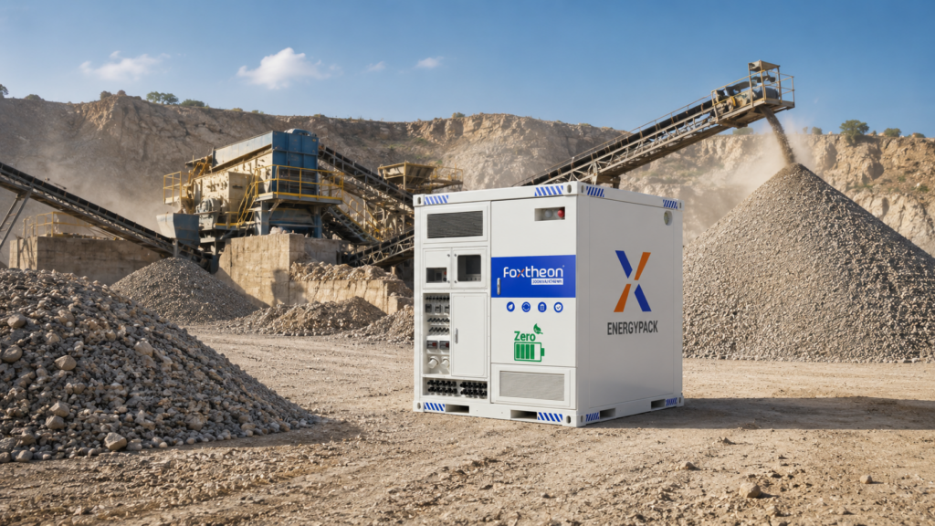
Heavy mining setups rely on ball mills, crushers, and haulage equipment that create massive, short-duration load spikes. Running pure generator setups requires keeping extra engines online as spinning reserve just to absorb these shocks. Incorporating energy storage through a modernized hybrid power framework lets the battery act as the primary dynamic reserve. This allows the facility to shut down unneeded generator capacity, keeping the remaining engines loaded efficiently without risking load-shedding events.
Edge-of-Grid Industrial Feeders
Manufacturing facilities tied to long, high-impedance distribution feeders frequently experience voltage drop, poor power factor, and unannounced power interruptions. An integrated on-site setup acts as an active power quality filter during normal operation, injecting reactive power to stabilize local bus voltage. If the main utility connection fails, the microgrid controller opens the motorized tie breaker, and the grid-forming PCS seamlessly assumes voltage reference for uninterrupted islanded operation.
Rapid-Deployment Hybridization Infrastructure
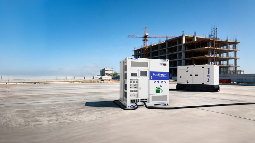
Temporary, modular generation systems used in infrastructure construction, disaster recovery, and remote oil and gas fields benefit from containerized integration. Modular platforms from Foxtheon package the inverter, storage cells, fire suppression, and intelligent dispatch controllers into transportable ISO shipping containers. These skid-mounted systems plug straight into mobile rental diesel generators, reducing run-hours and stretching out maintenance intervals without complicated on-site engineering.
Engineering Procurement and Manufacturer Evaluation
Specifying balance-of-plant components for multi-source systems requires looking beyond nominal nameplate ratings. Engineering teams must evaluate suppliers on deep hardware interoperability, communication standards, and rigorous factory testing.
Microgrid Controller Communication Protocols
A multi-source system is only as reliable as its communications network. Suppliers must provide open-architecture interfaces that support fast data exchange without vendor lock-in:
- Deterministic Networks: Real-time power balance requires low-latency protocols such as Modbus TCP/IP, EtherCAT, or CAN 2.0B between the master microgrid controller, the BESS, and the PV inverters, keeping loop cycle times under 20 milliseconds.
- Substation Interoperability: For medium-voltage utility-interconnected projects, the control platform should support IEC 61850 and DNP3 protocols to interface directly with remote telemetry units (RTUs) and protection relays.
Factory Acceptance Testing (FAT) Protocols
Before hardware ships to remote sites, vendors must perform complete, integrated system testing:
- Hardware-in-the-Loop (HIL) Simulation: The microgrid controller and PCS should be connected to digital real-time simulators to test system stability during simulated fault conditions, sudden solar loss, and full-load generator trips.
- Temperature Chamber Testing: Inverters and battery modules must operate under sustained high temperatures and thermal cycles to confirm their real-world thermal models and cooling design.
By treating legacy generator hardware as a valuable anchor asset within an optimized, multi-source framework, industrial operators can build clean, reliable power systems. Integrating resilient energy storage, advanced solar modules, and responsive controls cuts maintenance overhead, maximizes generation efficiency, and guarantees rock-solid power quality across the facility life cycle.
Frequently Asked Questions
Q1: How does a hybrid power system prevent diesel generator reverse power issues during high solar irradiance?
A1: An active Energy Management System (EMS) monitors the power flow at the generator output terminals using high-speed directional power meters. If solar output begins to exceed the facility load and the battery approach full charge, the controller quickly throttles back the solar inverters or directs the surplus into the battery via fast Modbus or CAN controls. This ensures power never flows back into the generator alternator, which would otherwise trigger the reverse-power relay (ANSI 32) and take the engine offline.
Q2: Can hybrid power configurations function without a continuous reference signal from a diesel generator?
A2: Yes, provided the system includes battery inverters capable of true grid-forming (GFM) control. In this mode, the inverter acts as an independent voltage source, setting the local voltage and frequency using droop control or virtual synchronous machine algorithms. The diesel engines can then be completely shut down during periods of high solar production, leaving the system to run purely on renewable power and battery storage until load demands call for extra generation.
Q3: What role does spinning reserve play in an industrial microgrid, and how does battery storage address it?
A3: Spinning reserve is the unused, online generation capacity kept idling to absorb sudden load spikes or unexpected generation drops. In traditional setups, this requires keeping extra generators running at low, inefficient load factors. A battery storage system acts as virtual spinning reserve, using the fast sub-cycle response of its power conversion system to inject power instantly. This covers transient loads and gives offline generators enough time to start and sync up only when genuinely needed.
Q4: Why is lithium iron phosphate (LiFePO4) preferred over other chemistries for industrial energy storage?
A4: LiFePO4 offers superior chemical, thermal, and mechanical stability compared to nickel-based chemistries (such as NMC or NCA). The strong covalent bonding in its phosphate structure gives it a high thermal runaway threshold and releases minimal oxygen even during high-temperature events. It also delivers thousands of operational cycles under deep depth-of-discharge (DoD) conditions, providing the durability and long calendar life required for demanding industrial applications.
Q5: How does hybridization resolve engine maintenance issues related to low-load operation?
A5: Diesel engines running below 30-40% load suffer from poor piston ring sealing, crankcase oil dilution, and unburned fuel collecting in the exhaust manifolds (wet stacking). By integrating energy storage, the hybrid controller diverts excess generator power to charge the battery bank whenever load demand drops. This artificial load keeps the engine running inside its ideal 70-85% brake-specific fuel consumption window, ensuring complete combustion and drastically reducing soot buildup and maintenance overhead.
Technical Project Inquiries
To consult with an engineering specialist regarding microgrid control integration, energy storage hardware selection, or generator synchronization for industrial facilities, submit your project single-line diagrams (SLD) and load profile specifications directly to the technical application team: Foxtheon Engineering & Solutions Support.