
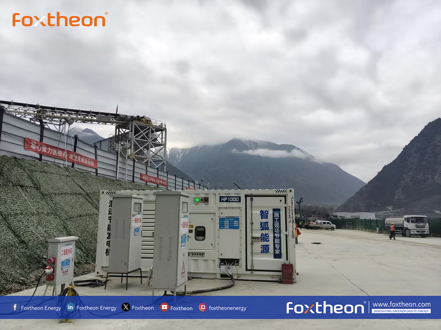
Decentralized industrial electrification demands power delivery systems that balance reliability, responsiveness, and fuel management. Traditional internal combustion engine generator sets (gensets), whether running on diesel, natural gas, or biofuels, have long served as primary off-grid utilities. However, dynamic fluctuations in electrical loads often force these units to operate outside their optimal efficiency curve. Running engines at low operational loads causes poor fuel combustion, carbon buildup, and accelerated mechanical degradation. The technical integration of an electrochemical energy storage system with dynamic generation assets—forming an integrated hybrid generator—addresses these mechanical constraints while enhancing power stability.
This technical analysis examines the functional integration of gensets with battery storage, reviewing inverter topologies, microgrid automation, enclosure structural engineering, and standard industrial deployment protocols.
Mechanical-Electrical Baseline: Genset Operation and Energy Storage Integration
Conventional reciprocating combustion engines are mechanically optimized to operate at 70% to 85% of their continuous rating. When loads drop below 30%, internal cylinder temperatures fall, preventing piston rings from sealing correctly. This leads to wet stacking, unburned fuel entering the exhaust stream, and fouled injectors. Conversely, sudden inrush currents from inductive loads, such as electric motors or industrial compressors, cause immediate frequency dips and voltage sags that can destabilize the distribution bus.
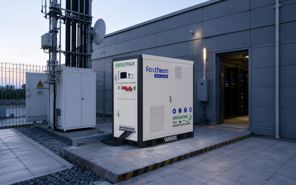
A hybrid generator resolves this operational mismatch by decoupling power generation from real-time electrical consumption. In this architecture, the combustion engine does not follow every minor perturbation of the load profile. Instead, an electrochemical energy storage system (ESS), typically utilizing lithium iron phosphate (LiFePO4) chemistry, acts as a high-speed dynamic buffer. When loads drop, excess energy produced by the generator running at its peak brake-specific fuel consumption (BSFC) point is diverted into the battery bank. When load spikes occur, the battery discharges synchronously through an industrial bidirectional inverter, supplying instant active power without requiring the mechanical engine to instantly step up its throttle.
Standards outlined by organizations such as the International Organization for Standardization (ISO 8528) categorize reciprocating engine performance classes. Incorporating battery storage into the architecture allows low-emission or standard diesel packages to consistently perform within ISO 8528-5 Class G3 parameters, preserving power quality under high step-load variations.
Power Conversion Systems (PCS) and Inverter Topologies
The operational capability of hybrid power equipment relies heavily on the Power Conversion System (PCS). Integrating direct current (DC) storage with alternating current (AC) distribution lines necessitates bidirectional inverters capable of sub-cycle switching times. In modern decentralized topologies, two primary control methodologies dictate system stability:
- Grid-Following (Current Source) Inverters: These units synchronize their output voltage and frequency with an existing AC voltage reference provided by the mechanical genset. The inverter injects controlled current into the bus to supplement load demands or absorb surplus power. While functionally sound, grid-following systems depend on the mechanical engine to maintain system inertia and voltage regulation.
- Grid-Forming (Voltage Source) Inverters: Utilizing droop control or virtual synchronous machine (VSM) algorithms, grid-forming inverters establish the AC bus voltage and frequency autonomously. Under this design, the hybrid generator can supply power to field equipment with the mechanical combustion engine completely deactivated. The engine starts only when the battery state of charge (SoC) reaches a programmed threshold or when sustained baseline demands exceed the continuous inverter rating.
Field installations governed by IEEE technical guidelines require high harmonic mitigation and phase balancing. Modern industrial inverters utilize multi-level pulse-width modulation (PWM) switching paired with comprehensive LC or LCL filtering networks to maintain Total Harmonic Distortion (THD) below 3% at full rated output, preventing nuisance tripping of downstream programmable logic controllers (PLCs) and sensitive telemetry units.
Structural Fabrication, Metallurgy, and Enclosure Engineering
Industrial power assemblies encounter demanding operating conditions, including mining dust, marine humidity, and extreme temperature ranges. Structural durability and thermal enclosure management are fundamental engineering factors determining operational life.
Chassis and Panel Metallurgy
Chassis assemblies rely on heavy-gauge structural channel steel (Q235B or equivalent structural grades) treated with hot-dip galvanizing to resist structural twisting during frequent transport and crane rigging. Canopy panels are predominantly manufactured from 2.0 mm to 3.0 mm electro-galvanized sheet steel or 5052-H32 marine-grade aluminum alloy. Aluminum construction provides superior resistance to chloride-induced pitting in coastal deployments and reduces gross weight for mobile applications.
Surface Treatments and Environmental Ingress
Coating systems must comply with ISO 12944 classifications for atmospheric corrosivity:
- C3 (Medium Industrial): Standard multi-stage iron-phosphate pretreatment followed by electrostatically applied polyester powder coating cured at high temperatures, offering nominal dry film thickness (DFT) between 80 and 120 microns.
- C5-M (Marine/Offshore): Zinc-rich epoxy primer followed by polyurethane topcoats, exceeding 240 microns DFT to resist sustained salt spray, sulfur dioxide exposure, and ultraviolet degradation.
- Ingress Protection: Ventilation louvers incorporate acoustic baffles and labyrinth filtration systems engineered to achieve IP54 or IP55 ratings, ensuring internal busbars and power electronics remain free from wind-driven moisture and particulate deposits.
Thermal Insulation and Acoustic Attenuation
Lithium iron phosphate cells require precise thermal regulation to avoid accelerated aging, demanding an internal environment maintained between 15°C and 35°C. Enclosures feature non-combustible Class A mineral wool or specialized aerogel insulation panels installed between structural double-skin walls. Acoustic dampening materials line the mechanical compartments, reducing continuous engine noise levels to below 65 dBA at 7 meters, facilitating operations in municipal environments or continuous-shift operations.
Dynamic Control Automation and Operational Dispatch
System reliability depends directly on the supervisory control system. Programmable automation controllers (PACs) and microgrid controllers manage high-speed data exchanges between the Engine Control Unit (ECU via J1939 CAN bus), the Battery Management System (BMS via Modbus TCP or CANopen), and the PCS.
Pioneering energy hardware developers such as Foxtheon design dedicated power management logic that continuously monitors system variables, executing prioritized control sequences:
- Dynamic Peak Shaving: When intermittent loads (e.g., motor starts, site hoisting) generate amperage spikes, the energy storage system responds within milliseconds to supply instantaneous current, keeping the mechanical engine load stable.
- Automatic Engine Optimization: If site demand falls below 40% of the combustion engine’s rated continuous output, the automation system commands the engine to recharge the storage pack at its optimal fuel-conversion point, subsequently shutting the engine down entirely once fully charged.
- Silent Hours Scheduling: For noise-restricted parameters, site controllers prioritize battery-only dispatch, maintaining low-noise operations while tracking capacity margins to schedule mandatory regeneration cycles.
- Unbalanced Phase Stabilization: On single-phase imbalances within three-phase networks, the inverter dynamically compensates per-phase currents, preventing the mechanical alternator from experiencing rotor overheating caused by negative sequence currents.
Industrial Applications and Load Profiles
Deploying a hybrid generator requires matching the electrical architecture to the site’s dynamic load signature.
Heavy Construction and Tower Crane Operations
Tower cranes, hoists, and concrete pumping stations demand massive instantaneous current during motor acceleration, followed by prolonged periods of negligible load or mechanical idling. A traditional generator must be sized to meet the maximum peak inductive demand, resulting in inefficient, low-load running for much of the shift. In a hybrid setup, a smaller primary combustion engine supplies base energy, while the inverter injects the required peak kVA for motor startup directly from the storage buffer.
Remote Industrial Microgrids and Exploration
Exploration bases, remote extraction operations, and field telecommunication hubs present asymmetrical loads with high day-to-night variance. Research provided by the National Renewable Energy Laboratory (NREL) confirms that continuous generator operation at low load factors substantially accelerates engine wear and increases logistical maintenance burdens. Operating a hybrid configuration permits the engine to run intermittently at peak efficiency, extending standard oil drain, filter replacement, and top-end overhaul intervals.
Temporary Infrastructure and Municipal Civil Works
Urban utility maintenance, trackside rail works, and emergency infrastructure repairs enforce stringent municipal limits on continuous noise and emissions. The dual-mode operational capability allows operators to run on battery reserves during nighttime hours and run the mechanical asset during designated daytime windows, satisfying both civil requirements and site power continuity.
Supplier Evaluation and Technical Validation Framework
Specifying hybrid generation hardware requires structured technical evaluation beyond standard factory datasheets. Engineering teams must review design configurations to ensure system compatibility and equipment longevity.
Suppliers must demonstrate stringent Factory Acceptance Testing (FAT) records, confirming full-load dynamic step tests (0% to 100% to 0%), switchgear thermal rise documentation, and comprehensive harmonic distortion reports. Verification of the Battery Management System architecture must reveal cell-level voltage and temperature monitoring, accompanied by multi-tier electrical isolation mechanisms (contactors, high-rupture-capacity fuses, and shunt trips).
Manufacturing firms like Foxtheon construct these integrated units with unified cooling circuits, ensuring high thermal isolation between power electronics, high-voltage battery racks, and mechanical engine bays. Furthermore, evaluating switchgear assemblies requires verification of compliance with IEC 61439 standards, confirming internal separation forms (Form 2b or Form 4b) to protect maintenance technicians during diagnostic evaluations.
A well-engineered hybrid generator pairs verified mechanical sub-assemblies with robust industrial inverters, providing consistent performance across demanding multi-year deployment lifecycles.
Technical Inquiries and System Specification Support
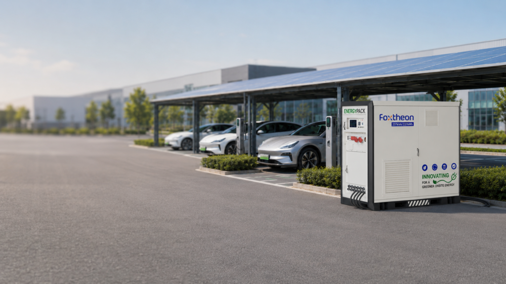
Industrial operators, microgrid engineers, and equipment fleets seeking custom engineering schematics, power sizing analyses, or integration configurations for specialized operating parameters are invited to submit project profiles for evaluation.
Please transmit site electrical load profiles, continuous kVA requirements, peak inductive start surges, and environmental conditions to the engineering applications group at Foxtheon for system evaluation.
Frequently Asked Questions
Q1: How does a hybrid generator handle high inductive inrush currents from industrial electric motors?
A1: Inductive motor starts create short-duration inrush currents that can reach six to eight times the continuous running amperage. In a hybrid system, the bidirectional inverter delivers instantaneous current from the high-discharge-rate battery bank within sub-cycle response times. This eliminates the voltage drop and frequency droop typically experienced when an isolated mechanical alternator responds to sudden step-loads.
Q2: Can hybrid power systems integrate with supplementary renewable assets such as on-site solar PV?
A2: Yes. The control infrastructure and DC bus architecture of these systems can accommodate direct coupling with photovoltaic arrays via Maximum Power Point Tracking (MPPT) charge controllers, or AC coupling via standard solar inverters. The internal microgrid controller balances solar input, battery storage capacity, load demand, and generator dispatch in a unified operational scheme.
Q3: What battery chemistry is standard in an industrial hybrid generator, and why?
A3: Lithium Iron Phosphate (LiFePO4) is the recognized standard for industrial hybrid generator units due to its high thermal stability, extended cycle life (often exceeding 4,000 to 6,000 cycles at 80% Depth of Discharge), and resilient chemical bonds that resist thermal runaway under high-load charging and discharging operations.
Q4: How is engine wet stacking prevented in dynamic off-grid setups?
A4: Wet stacking is prevented by programming the control system to prevent the engine from operating below a predetermined load threshold (typically 40% to 50%). When consumer demand falls below this setpoint, the excess alternator capacity is channeled directly into charging the battery storage bank, ensuring the engine consistently operates within its optimal thermal and mechanical combustion window.
Q5: What routine maintenance protocols are required for the electrical storage component?
A5: Unlike the mechanical engine, which requires scheduled lubricating oil, coolant, and filter changes, the solid-state electrical storage system requires primarily non-invasive maintenance. Protocols involve scheduled visual inspections of terminal torque settings, cleaning or replacing enclosure air intake filters, checking coolant levels in liquid-cooled thermal management circuits, and analyzing BMS cell-balancing telemetry via system diagnostic interfaces.