The transition toward decentralized distribution networks demands robust buffer technologies capable of balancing supply fluctuations and demand spikes. Industrial facilities and grid operators face mounting pressure to maintain power quality while managing complex load profiles. Integrating a modern battery storage energy system into the existing electrical infrastructure has emerged as a reliable method to stabilize voltage, manage peak demand, and ensure operational continuity.
For engineering procurement professionals, selecting the appropriate architecture requires an analysis of cell chemistry, power electronics, and control software. These systems are no longer simple backup assets; they function as active thermal and electrical regulation hubs that interface directly with local distribution grids and onsite generation resources.
Battery Chemistry and Material Analysis
The core performance of any stationary storage system is determined by its electrochemical composition. While several chemistries exist, Lithium Iron Phosphate (LFP) and Nickel Manganese Cobalt (NMC) dominate the commercial sector. Each presents distinct trade-offs in thermal stability, degradation rates, and energy density.
Lithium Iron Phosphate (LFP) vs. Nickel Manganese Cobalt (NMC)
LFP chemistry utilizes an olivine crystal structure, which provides strong covalent bonds between phosphorus and oxygen atoms. This structural framework makes the cell highly resistant to oxygen release at elevated temperatures, raising the thermal runaway threshold to approximately 270°C. Consequently, LFP cells are highly suited for stationary applications where physical space is less constrained than in mobile applications, and safety is the paramount engineering priority.
Conversely, NMC chemistries offer higher volumetric energy density, making them suitable for space-constrained installations. However, their layered oxide structures are more prone to exothermic reactions at lower thermal thresholds (around 210°C). For large-scale industrial deployments, LFP is typically preferred due to its superior cycle life—often exceeding 4,000 to 6,000 cycles at an 80% Depth of Discharge (DoD)—compared to the 2,000 to 3,000 cycles typical of NMC formulations.
Anode and Cathode Material Quality
Beyond the basic chemistry, the processing of anode and cathode materials affects degradation kinetics. Advanced systems utilize synthetic graphite anodes with silicon-carbon composites to reduce volume expansion during lithiation. The choice of binder material and separator thickness also determines the internal resistance of the cell. Low internal resistance minimizes heat generation during rapid charge and discharge cycles, which directly translates to reduced auxiliary cooling load and higher round-trip efficiency.
The Three-Tier Architecture of a Stationary Storage System
A commercial-grade battery storage energy system consists of three integrated technology layers: the Battery Management System (BMS), the Power Conversion System (PCS), and the Energy Management System (EMS). Operational synergy among these layers is necessary to prevent premature cell degradation and maximize system efficiency.
1. Battery Management System (BMS)
The BMS operates at the lowest level, monitoring cell-level parameters including voltage, current, and temperature. Industrial systems developed by technical manufacturers like Foxtheon utilize a multi-tiered BMS architecture:
- Slave BMS (Module Level): Monitors individual cell voltages and balances charges using active or passive balancing topologies.
- Master BMS (Rack Level): Aggregates data from multiple modules, calculates State of Charge (SoC) and State of Health (SoH), and manages local contactors.
- System BMS (Container Level): Coordinates communication across all racks and interfaces directly with the master controller and thermal management systems.
2. Power Conversion System (PCS)
The PCS is the bidirectional inverter system responsible for converting Direct Current (DC) stored in the batteries to Alternating Current (AC) compatible with the grid or facility load. Modern PCS units utilize high-frequency switching topologies based on Silicon Carbide (SiC) or Insulated-Gate Bipolar Transistors (IGBTs). Key performance metrics for the PCS include:
- Four-Quadrant Operation: The capability to control both active power (P) and reactive power (Q), which is necessary for grid stabilization, voltage support, and power factor correction.
- Harmonic Distortion Control: Total Harmonic Distortion (THD) must be kept below 3% to comply with standards such as IEEE 519, preventing interference with sensitive industrial machinery.
- Response Time: Sub-millisecond response times are required for transient mitigation and seamless transition to islanded mode during grid outages.
3. Energy Management System (EMS)
The EMS acts as the system brain, running optimization algorithms to dispatch power based on external inputs such as electricity tariffs, weather forecasts, local load demands, and grid signals. The EMS communicates via standardized industrial protocols like Modbus TCP/IP, CAN bus, or IEC 61850. By coordinating the PCS and BMS, the EMS ensures that the battery operates within its optimal electrochemical parameters while maximizing operational benefits.
Industrial Application Scenarios and Operational Benefits
Deploying a battery storage energy system allows industrial operations to mitigate power supply variations and optimize energy consumption. The specific operational profile depends heavily on the facility’s load characteristics and regional utility structures.
Peak Shaving and Load Shifting
Industrial facilities often face significant demand charges based on their peak consumption window. Peak shaving involves discharging the battery system during periods of maximum power demand, artificially flattening the load curve seen by the utility. Load shifting, on the other hand, utilizes the battery to absorb energy during low-rate periods (e.g., nighttime) and discharge it during high-rate peak hours, lowering energy procurement costs without altering operational schedules.
Microgrid Integration and Backup Power
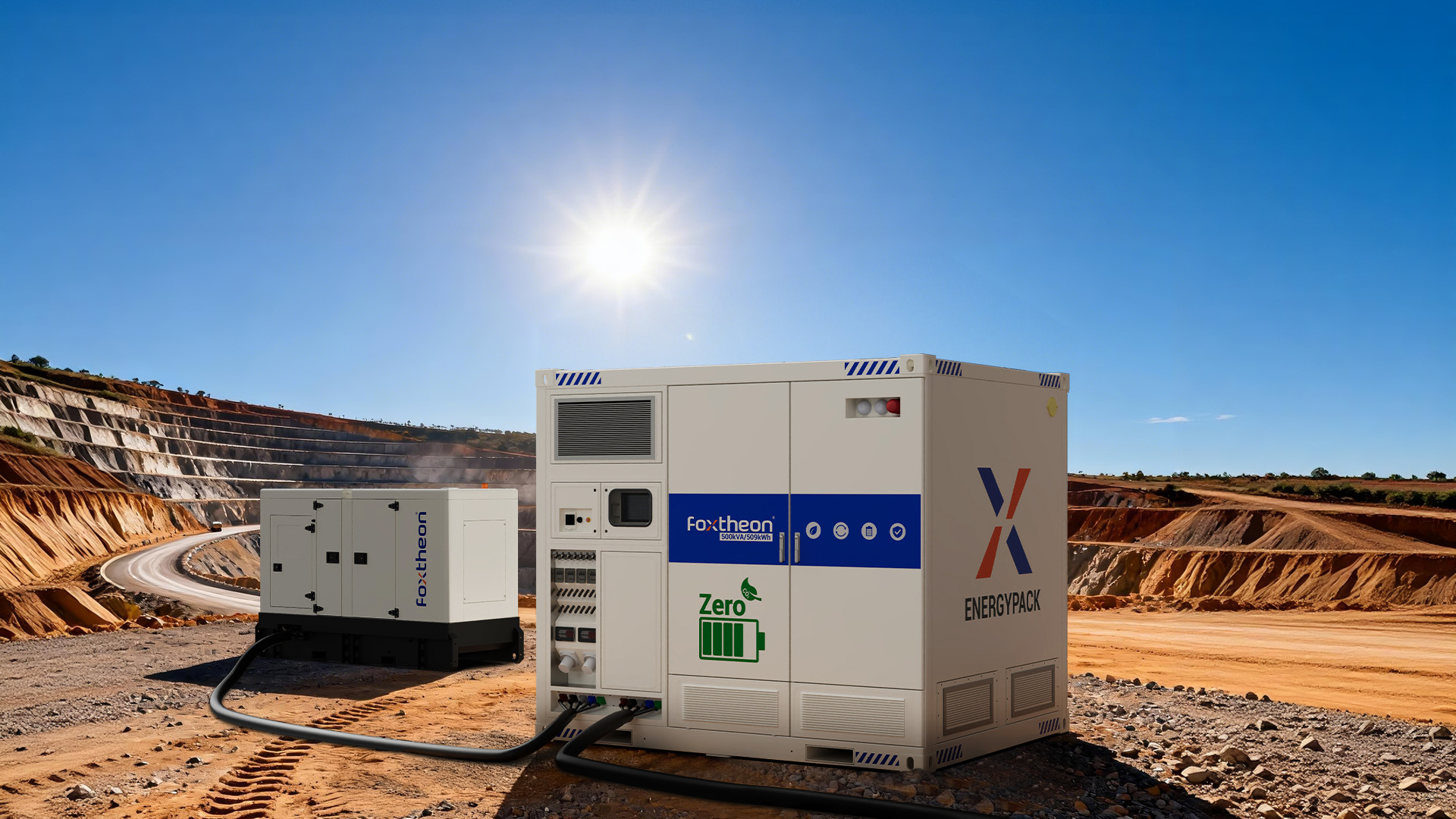
For remote operations or sites with unstable grid connections, a battery storage energy system serves as the anchor for a localized microgrid. It provides the reference voltage and frequency required for renewable assets, such as photovoltaic arrays, to operate in the absence of a utility grid. The integrated solutions provided by Foxtheon emphasize high safety margins and robust enclosure designs, ensuring reliable performance even in harsh environmental conditions.
When integrated into microgrids, these systems act as dynamic shock absorbers. They manage instantaneous load changes that would otherwise cause voltage sags or trigger safety shutdowns in sensitive industrial equipment.
Thermal Management and Safety Mechanisms
Thermal regulation is a primary factor determining the lifetime and safety of large-scale battery installations. High temperatures accelerate lithium plating and SEI (Solid Electrolyte Interphase) layer growth, leading to capacity fade and potential safety hazards. Low temperatures increase internal resistance, reducing charge acceptance and usable capacity.
Air Cooling vs. Liquid Cooling
Industrial systems employ either forced-air cooling or closed-loop liquid cooling. Forced-air cooling relies on HVAC systems and internal ducting to route air through the battery racks. While simpler in design, air cooling can result in thermal gradients of 3°C to 5°C across a single rack, leading to uneven cell aging.
Liquid cooling utilizes cold plates in direct contact with the battery cells or modules, circulating a glycol-water mixture. This method achieves high thermal heat transfer coefficients, keeping cell temperature variations within ±2°C across the entire container. A utility-scale battery storage energy system must operate under precise thermal control to ensure system longevity, making liquid cooling the industry standard for high-C-rate applications.
Multi-Layered Safety Protocols
To mitigate the risk of thermal runaway, modern systems employ a comprehensive, multi-layered containment strategy:
- Early Detection: Off-gas detection systems sense trace amounts of carbon monoxide and volatile organic compounds (VOCs) before any physical temperature rise or voltage drop occurs.
- Deflagration Prevention: Exhaust ventilation systems automatically purge the enclosure with inert gas or fresh air to prevent the accumulation of flammable gases.
- Fire Suppression: Integrated clean agent fire suppression (such as Novec 1230) or targeted water-mist systems isolate localized thermal events without damaging surrounding electrical equipment.
Sourcing, Quality Control, and Supplier Verification
Procuring utility-scale energy storage requires systematic verification of both product compliance and manufacturing capabilities. Unlike standard electrical distribution hardware, battery systems require deep integration across chemical, electrical, and software disciplines.
Crucial Standards and Certifications
Sourcing teams must verify that any prospective manufacturer holds international certifications verified by accredited third-party laboratories (such as TÜV, Intertek, or UL). Key standards include:
- UL 1973: Tests the safety of battery companion modules and racks under abnormal conditions, such as short circuits, overcharging, and mechanical stress.
- UL 9540 / UL 9540A: Evaluates the system-level safety of energy storage systems and analyzes thermal runaway fire propagation behavior within battery groups.
- IEC 62619: Specifies safety requirements for secondary lithium cells and batteries used in industrial stationary applications.
- UN 38.3: Verifies the safety of lithium batteries during transport under extreme vibration, temperature, and pressure conditions.
Engineering Competency and Integration Capabilities
Industrial purchasers should look beyond component specifications and evaluate a supplier’s engineering capability. A reliable partner must demonstrate competency in system modeling, short-circuit current analysis, and protection coordination. The advanced control topologies developed by Foxtheon allow seamless synchronization with existing medium-voltage switchgear, reducing onsite installation and commissioning times.
When assessing pricing structures, buyers should evaluate long-term maintenance requirements, spare parts availability, and software update policies. Transparent pricing structures typically separate the upfront containerized hardware capital expenditure from the ongoing service agreement costs, allowing for more predictable operational planning.
Integration with Existing Generator Assets
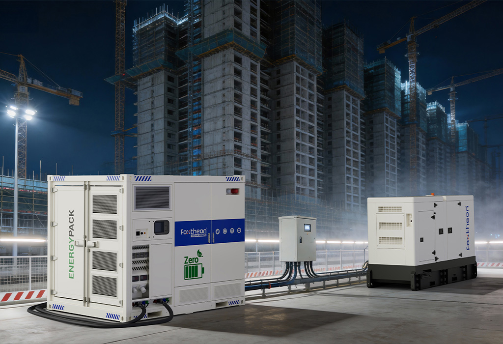
Implementing a battery storage energy system alongside existing reciprocating engines, such as diesel or natural gas generators, optimizes overall facility efficiency without requiring the retirement of functional power assets. Rather than seeking to replace traditional generators, stationary storage serves to complement them.
Generators operate most efficiently within a specific load range, typically between 70% and 90% of their rated capacity. When subjected to low load conditions (often during periods of low facility activity), diesel generators run inefficiently, leading to incomplete combustion and carbon build-up, commonly known as wet stacking. By integrating a storage system, the battery can absorb surplus power during low-load periods or supply necessary power during peak windows. This ensures the generator operates continuously within its optimal fuel-efficiency curve, reducing maintenance cycles and prolonging the operating life of the mechanical asset.
Frequently Asked Questions
Q1: How long does a commercial battery storage energy system typically last?
A1: The operational lifespan of a modern storage system is typically between 10 to 15 years, primarily governed by the degradation of the electrochemical cells. When using high-grade Lithium Iron Phosphate (LFP) chemistry, systems generally retain 70% to 80% of their nominal capacity after 4,000 to 6,000 full charge-discharge cycles under recommended operating temperatures.
Q2: Can a battery storage energy system operate in extreme climates?
A2: Yes, provided the system is equipped with an engineered thermal management system. For extreme environments, liquid-cooled enclosures with integrated insulation and internal heating elements are utilized to maintain battery cell temperatures within the optimal 15°C to 30°C window, even when ambient temperatures range from -30°C to 50°C.
Q3: What is the difference between C-rate and system capacity?
A3: System capacity, measured in kilowatt-hours (kWh) or megawatt-hours (MWh), represents the total quantity of energy stored. The C-rate defines the speed at which the system can be fully charged or discharged. For example, a 1C-rated 100 kWh battery can deliver 100 kW of power for 1 hour, whereas a 0.5C-rated system of the same capacity can deliver 50 kW for 2 hours.
Q4: How does a battery system coordinate with onsite solar PV?
A4: The EMS manages coordination by monitoring solar output and facility load in real-time. When solar generation exceeds the local load, the excess energy is routed to charge the battery. Conversely, during periods of cloud cover or after sunset, the battery discharges to maintain stable output, mitigating the intermittent nature of solar generation.
Q5: What are the main fire protection requirements for indoor battery installations?
A5: Indoor installations typically require compliance with NFPA 855 standards, which mandate structural fire barriers, minimum spacing between battery racks to prevent thermal runaway propagation, dedicated exhaust ventilation systems for gas venting, and integrated, automatic gaseous or water-mist fire suppression systems.
Industrial Inquiry and Technical Consultation
Engineering and procurement teams seeking to integrate advanced battery storage architectures into their existing electrical infrastructure can request detailed technical drawings, system sizing simulations, and compatibility documentation. Please submit your project specifications, including load profile data, peak demand limits, and environmental conditions, to our application engineering department.
Foxtheon Technologies
Email: info@foxtheon.com
Web: https://www.foxtheon.com/