
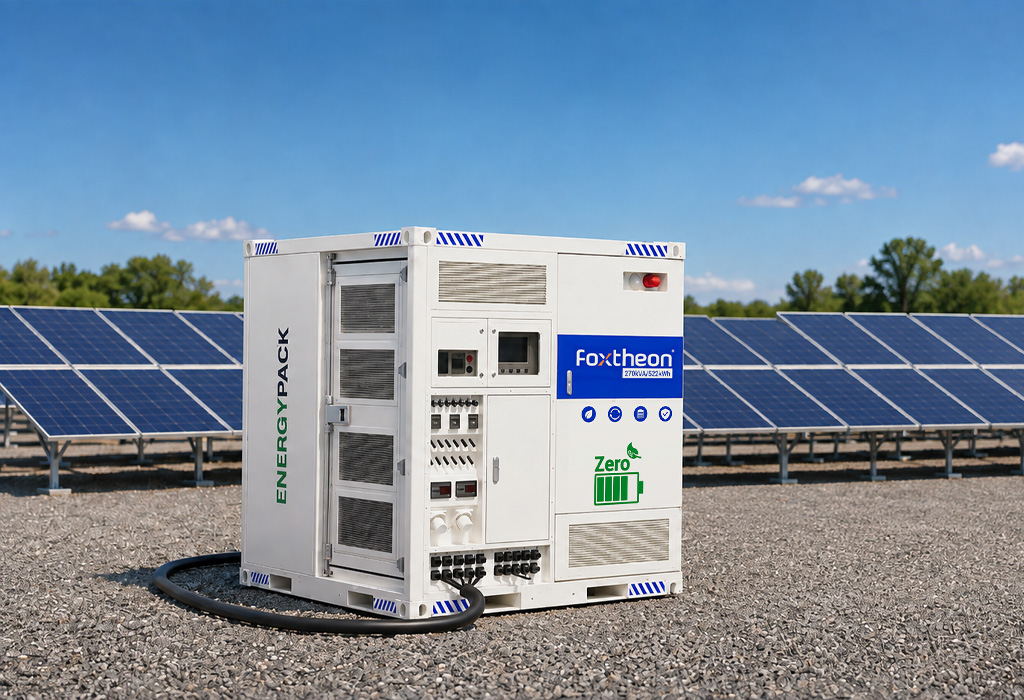
Industrial manufacturing plants, telecommunications backbones, healthcare centers, and high-density data hubs require uninterrupted operational stability. Grid disturbances, voltage sags, frequency deviations, and unplanned outages impose immediate mechanical stress on downstream equipment, causing line stoppages, data corruption, and batch failures. Mitigating these events requires the deployment of an engineered Emergency Power Supply capable of sub-cycle switching, sustained dynamic load acceptance, and stable voltage regulation under nonlinear load conditions.
Energy continuity has advanced beyond isolated reserve assets toward unified smart microgrids. Contemporary facilities combine diverse electrical assets—including existing reciprocating internal combustion engines, photovoltaic arrays, and utility feeds—with modern battery energy storage systems (BESS). Balancing transient response times with sustained runtime requires a granular understanding of power electronics topologies, electrochemical storage behavior, structural enclosure designs, and standardized factory acceptance protocols.
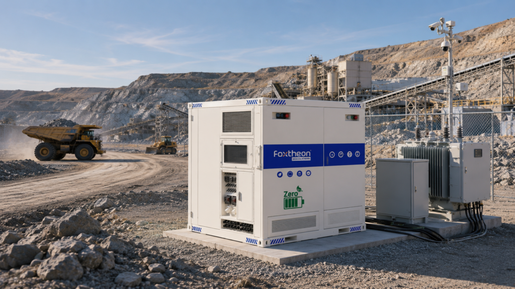
Power Conversion Topologies and Grid-Forming Controls
The primary baseline for any backup installation is its power conversion system (PCS) and transfer mechanism. Traditional backup schemes frequently experienced transfer delays ranging from tens of milliseconds to minutes, exposing sensitive supervisory control and data acquisition (SCADA) systems and variable frequency drives (VFDs) to zero-voltage dropouts. Industrial facilities avoid this interruption by deploying bidirectional, four-quadrant PCS units engineered for grid-forming (GFM) control regimes.
Grid-forming inverters establish steady-state voltage and frequency vectors rather than merely synchronizing with an existing external utility waveform (grid-following). When utility reference signals vanish, an engineered Emergency Power Supply leverages static transfer switches (STS) utilizing back-to-back silicon-controlled rectifiers (SCRs). This switchgear topology achieves transition periods below 4 to 10 milliseconds, comfortably within the tolerance curve defined by the Information Technology Industry Council (ITIC/CBEMA standards).
- Static Transfer Mechanics: Solid-state switching eliminates the mechanical inertia inherent to mechanical automatic transfer switches (ATS), preventing inrush-induced phase divergences during utility loss.
- Harmonic Attenuation: Advanced PCS hardware incorporates multi-level inverter topologies (such as neutral point clamped three-level designs) operating at pulse-width modulation (PWM) carrier frequencies above 3 kHz. This configuration suppresses total harmonic distortion (THD) below 3% under linear loads and below 5% under distorted, non-linear industrial rectify loads.
- Dynamic Slew Rates: Fast current-loop controllers allow energy storage inverters to swing from maximum charging mode to full discharge capacity in fractions of an AC cycle, dampening generator ramp-rate stress during sudden block loading.
Electrochemical Selection: LFP Stability in Standby Configurations
Energy storage performance rests on battery chemistry. While legacy configurations historically relied on nickel-cadmium or valve-regulated lead-acid (VRLA) banks, these chemistries struggle with wide ambient temperature envelopes, heavy footprints, and shortened operational lifecycles under continuous float-charge regimes. Modern industrial specifications favor Lithium Iron Phosphate (LiFePO4, or LFP).
LFP chemistry features an olivine crystal structure characterized by robust covalent bonding between phosphorus and oxygen atoms. This structural matrix resists structural degradation during sustained high-voltage float conditions, offering superior thermal runaway resistance compared to nickel-manganese-cobalt (NMC) or older chemistries. The thermal runaway threshold for LFP sits safely above 270°C, providing higher intrinsic physical stability during continuous standby states.
When selecting cells for an industrial Emergency Power Supply, engineering teams evaluate cycle life curves at designated depths of discharge (DoD) alongside C-rate throughput profiles. Standby systems typically require brief high-rate current bursts (1C to 2C discharges) to absorb transient electric motor starting currents, followed by regulated 0.2C to 0.5C sustained delivery until alternative sources engage or utility power normalizes. Integrated active battery management systems (BMS) continuously sample microvolt-level potential differences across series-connected cell strings, actively redistributing charge to balance state-of-charge (SoC) parameters and mitigate localized cell degradation.
Panel Materials, Enclosure Metallurgy, and Environmental Hardening
Internal power components rely entirely on structural protection against moisture, airborne contaminants, and physical stress. Deploying battery-backed systems in coastal, chemical, or arid environments requires careful attention to metallurgical fabrication and surface treatment regimes.
Outdoor cabinets and modular energy containers utilize either heavy-gauge electro-galvannealed steel (minimum 2.0 mm to 3.0 mm nominal wall thickness) or marine-grade 5052-H32 aluminum alloys. Galvannealed carbon steels undergo automated, multi-stage conversion coatings followed by zinc-rich thermoset powder coatings. This finishing process achieves corrosion resistance ratings exceeding 1,000 hours of continuous salt spray testing per ASTM B117 standards, meeting ISO 12944 C4 or C5-M atmospheric corrosivity categories.
Thermal regulation directly impacts internal electronics longevity. Sealed IP55, IP66, or NEMA 3R/4 enclosures isolate sensitive battery modules and inverters from ambient particulates and blowing precipitation. Heat extraction balances two primary thermal management approaches:
- Forced-Air Thermal Conditioning: Closed-loop industrial air handling systems circulate internal air over redundant evaporator coils, ensuring zero exchange with contaminated external air. Dual-compressor designs prevent single-point thermal failures while operating across wide external temperatures (-20°C to +50°C).
- Direct-to-Plate Liquid Cooling: High-density energy storage arrays integrate closed-loop liquid cooling cold plates directly beneath cell groupings. Utilizing a non-conductive glycol-water mixture with variable-speed precision pumps, liquid systems maintain inter-cell temperature differentials within a strict 2°C to 3°C window. This tight thermal regulation extends cell operating lifespans and prevents localized thermal hot spots.
Through robust enclosure engineering and advanced manufacturing controls, energy architecture developed by Foxtheon incorporates heavy-gauge external protection and isolated compartment segmentation to support reliable deployment in severe environmental conditions.
Integration Strategies: Hybrid Operations with Internal Combustion Gensets
Modern microgrid architectures coordinate multiple generation sources rather than operating single isolated reserves. Many industrial facilities maintain substantial existing assets, such as diesel or natural gas generator sets. Integrating modern battery storage with these engine assets establishes a resilient, hybrid generation network that optimizes overall operational stability.
Internal combustion engines exhibit mechanical inertia and delay periods when subjected to large step loads. Applying an 80% to 100% block load to a cold standby engine can cause transient frequency dips below 57 Hz or complete thermal stalls. Integrating an Emergency Power Supply directly onto the main low-voltage or medium-voltage switchgear bus transforms system transient performance.
The battery system functions as a dynamic shock absorber. When a large industrial pump or chiller activates, the inverter injects instantaneous active power (kW) and reactive power (kVAR), effectively smoothing the step-load demand curve. This ramp-rate control allows the mechanical generator to modulate its throttle gradually, preventing engine lugging and maintaining the local electrical island at 60 Hz ± 0.05 Hz. In multi-source installations, microgrid controllers from Foxtheon continuously coordinate frequency-droop and voltage-droop schedules between the inverter and the engine governor, providing seamless load allocation without proprietary communication cross-talk.
Technical Specification Comparison: Standby Systems
System architects must evaluate core performance attributes across different storage and generation technologies to match specific facility load profiles:
| Performance Attribute | VRLA Battery Bank | LFP Solid-State Battery System | Direct-Drive Standby Genset |
|---|---|---|---|
| Response / Switching Time | Sub-cycle (< 10 ms via UPS) | Sub-cycle (< 5 ms via static PCS) | 8 to 30 seconds (crank to sync) |
| Dynamic Step-Load Acceptance | Moderate (voltage sag prone) | Exceptional (100% instantaneous step) | Constrained (requires staged loading) |
| Thermal Sensitivity | High (ideal: 20°C to 25°C) | Moderate (actively managed to 15°C–35°C) | Broad (engine coolant block heaters needed) |
| Physical Footprint & Weight | Extremely Heavy / Large Volume | Compact / High Volumetric Density | Moderate Footprint / Dynamic Mechanical Loads |
| THD Under Non-Linear Loads | Dependent on downstream inverter | < 3% (via advanced active filtering) | 5% to 12% (based on alternator sub-transient reactance) |
Procurement and Supplier Evaluation Matrix
Procuring utility-scale and industrial equipment requires comprehensive engineering verification rather than simple nameplate capacity matching. Engineering, procurement, and construction (EPC) professionals must validate design claims through international testing documentation and structural compliance reports.
Supplier selection begins with verification against recognized global safety standards. For battery-based equipment, systems must carry certifications under UL 9540 (Energy Storage Systems and Equipment) and UL 1973 (Batteries for Use in Stationary Applications). Furthermore, full-scale thermal runaway fire propagation testing under UL 9540A must be documented at the cell, module, unit, and installation levels. These reports clarify deflagration venting volumes and safe clearance distances for indoor and outdoor installations.
Evaluating an Emergency Power Supply vendor also involves inspecting internal subsystem separation. High-reliability architectures feature strict physical isolation between the low-voltage control cabinets, the high-voltage direct current (DC) battery bus, and the AC conversion switchgear. Galvanic isolation transformers, high-speed DC branch fuses with appropriate breaking capacities (typically > 100 kA at 1000 VDC or 1500 VDC), and integrated aerosol or clean-agent fire suppression systems represent standard engineering expectations.
Factory Acceptance Testing (FAT) records must demonstrate real-world performance under diverse electrical conditions. Validated test documentation must prove:
- Four-quadrant operation across leading and lagging power factors (0.8 leading to 0.8 lagging).
- Short-circuit withstand capabilities rated to match upstream switchgear fault clearing times without uncommanded disconnects.
- Interoperability under standard open protocols such as Modbus TCP/IP, DNP3, and IEC 61850 for seamless DCS/SCADA network integration.
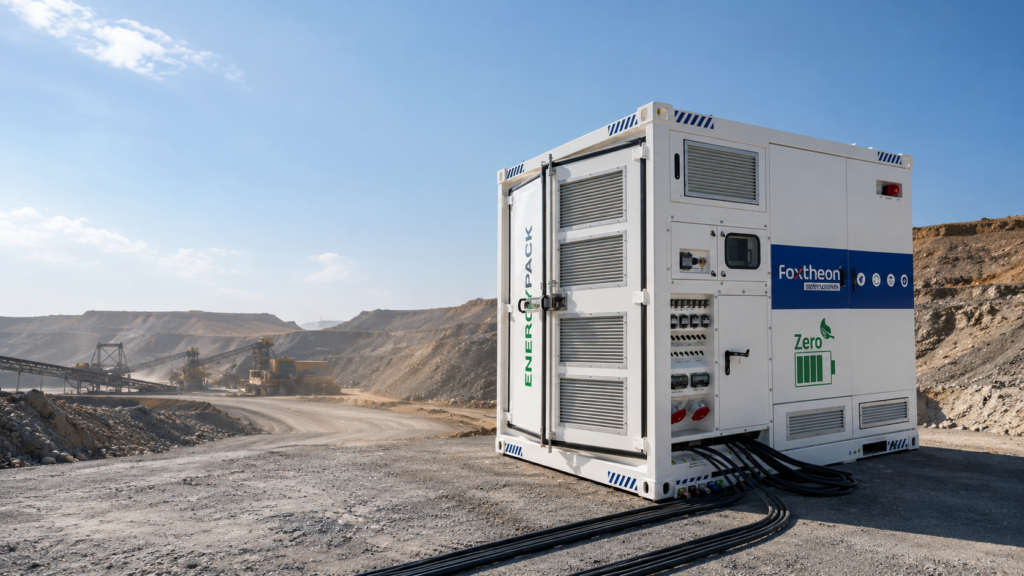
System Sizing Considerations for Industrial Inductive Loads
Accurate sizing requires detailed evaluation of steady-state and transient load characteristics. Sizing a system strictly based on running nameplate kilowatt values frequently results in operational tripping when high-inertia inductive motors cycle on.
Induction motors exhibit locked-rotor amps (LRA) reaching five to eight times their full-load running amps (FLA). When these loads start across-the-line, the low sub-transient impedance of the power source dictates the magnitude of the resulting bus voltage dip. If the source cannot supply the requisite starting kVA, system voltage drops below the low-voltage dropout thresholds of sensitive control relays and variable frequency drives, triggering a broader facility shutdown.
Integrating a modern Emergency Power Supply resolves these issues by supplying instantaneous kVAR injection. Advanced power conversion controls continuously monitor output current phase angles, automatically delivering reactive current pulses that satisfy the transient magnetization demands of inductive equipment without stressing parallel-running engines or primary utility feeds.
Frequently Asked Questions
Q1: What are the differences between an Emergency Power Supply (EPS) and an Uninterruptible Power Supply (UPS)?
A1: An industrial EPS is designed for sustained, comprehensive facility support, often handling full facility power needs across extended disruptions while coordinating directly with parallel generation assets. A UPS is traditionally a localized, short-duration bridge designed to preserve sensitive computing or instrumentation loads for brief windows, providing clean power long enough for standby generators to start or for systems to execute an orderly shutdown.
Q2: How does a solid-state EPS protect operations against micro-outages and voltage sags?
A2: Micro-outages and voltage sags lasting mere cycles can cause contactors to drop out and shut down modern automated production lines. Systems incorporating sub-cycle static transfer switches and four-quadrant bidirectional inverters continuously monitor incoming AC waveforms. When voltage drops below pre-set tolerances, the system transitions to battery power in less than 4 milliseconds, maintaining an unbroken waveform without line dropouts.
Q3: Why is Lithium Iron Phosphate (LiFePO4) preferred over alternative lithium-ion chemistries for industrial backup systems?
A3: LiFePO4 offers superior chemical, thermal, and mechanical stability compared to nickel-based chemistries. Its high thermal runaway onset point (>270°C) and resistance to oxygen release during thermal events minimize hazard profiles in high-density facilities. Additionally, it delivers exceptional calendar and cycle lifespans under continuous float-charge operations without suffering from memory degradation.
Q4: Can a battery-based emergency system operate in parallel with on-site diesel generator assets?
A4: Yes. Modern smart microgrid controllers enable tight synchronization between battery inverters and internal combustion engines. In this architecture, the battery storage handles instantaneous transient step loads and dynamic load spikes, allowing the mechanical generator to ramp gradually and operate in its most efficient fuel-consumption and emission zones.
Q5: What enclosure ingress protection ratings are recommended for outdoor industrial installations?
A5: Outdoor installations require a minimum of NEMA 3R or IP55 ingress protection to guard against driving rain, dust, and particulate ingress. In severe coastal environments, chemical processing plants, or areas with high airborne particulate loads, specifications should require IP66 or NEMA 4X enclosures constructed from 5052-H32 aluminum or galvannealed steel treated with marine-grade C4/C5-M powder coating systems.
Engineering Inquiries & Specification Review
Detailed architectural sizing, switchgear topology selection, single-line diagram (SLD) development, and technical data sheets are available directly through the Foxtheon technical applications engineering division. Submit full load profiles, one-line diagrams, and project environmental parameters to our engineering team for comprehensive system modeling and code compliance verification.