Modern electrical networks demand advanced flexibility as power generation models transition toward decentralized, multi-source architectures. Industrial and commercial operations require robust infrastructure to manage load variability, maintain voltage stability, and ensure operational continuity. Implementing a high-capacity battery energy system has emerged as a primary strategy for balancing supply and demand at the local level. These systems serve as dynamic buffers, storing energy during periods of low demand or high generation and discharging it when the local grid experiences stress or peak pricing tariffs.
For system integrators, electrical engineers, and facility managers, selecting the appropriate technology requires a deep understanding of electrochemical behavior, system topology, thermal management, and control strategies. Manufacturers like Foxtheon provide modular, scalable platforms designed to integrate with existing infrastructure, ensuring that commercial enterprises can maintain power quality while optimizing their operational efficiency.
Technical Framework of Modern Battery Energy Systems
Electrochemistry and Cell Topologies
The performance profile of any stationary storage solution is governed by its underlying cell chemistry. In commercial and industrial (C&I) environments, Lithium Iron Phosphate (LiFePO4 or LFP) has become the industry standard for stationary applications. This preference is driven by several key electrochemical characteristics:
- Thermal Stability: LFP chemistry offers a high thermal runaway threshold (typically around 270°C), making it inherently safer than Nickel Manganese Cobalt (NMC) formulations in high-capacity installations.
- Cycle Life: LFP cells regularly achieve between 4,000 and 6,000 cycles at an 80% Depth of Discharge (DoD) before capacity degrades to 80% of its original rating.
- Voltage Profile: LFP exhibits a flat discharge curve, providing stable nominal voltage throughout the majority of the discharge cycle, which simplifies inverter design and operation.
The chemistry chosen for a modern battery energy system dictates its C-rate capability, which defines the rate at which a battery is charged or discharged relative to its maximum capacity. A system with a 1C rating can fully discharge its nominal capacity in one hour, whereas a 0.5C system requires two hours. Industrial peak-shaving applications typically rely on 0.5C to 1C configurations, balancing instantaneous power delivery with long-term cell health.
The Role of the Battery Management System (BMS)
The Battery Management System is the primary intelligence unit of the storage architecture. It monitors, manages, and protects individual cells, modules, and entire packs from operating outside safe limits. The BMS performs several primary functions:
- State of Charge (SoC) Estimation: Utilizing advanced algorithms such as Kalman filtering, the BMS calculates the instantaneous energy remaining in the system, preventing overcharging or overdischarging.
- State of Health (SoH) Tracking: By tracking impedance changes, capacity fade, and temperature history, the BMS projects the remaining useful life of the cells.
- Cell Balancing: Passive or active balancing mechanisms are employed to equalize voltage across all cells in a series string, maximizing usable capacity and preventing localized cell degradation.
- Safety Protocols: If a parameter such as voltage, current, or temperature exceeds predefined thresholds, the BMS initiates contactor isolation to protect the system from thermal runaway or electrical faults.
Application Integration and Operational Strategies
Peak Shaving and Load Leveling in C&I Environments
Commercial and industrial facilities face demand charges based on their highest power consumption intervals. By implementing a battery energy system, operators can execute peak-shaving protocols. The control system continuously monitors utility power intake at the point of common coupling (PCC). When facility load exceeds a predetermined threshold, the storage system discharges to supply the excess power locally, flattening the grid-drawn demand curve.
Load leveling, by contrast, focuses on shifting large blocks of energy over extended periods. The system charges during off-peak hours when electricity costs are low or when localized renewable assets (such as solar PV arrays) are overproducing. This stored energy is then discharged during peak-tariff hours, lowering total utility consumption without altering the facility’s operational schedule.
Microgrid Integration alongside Existing Generator Infrastructure
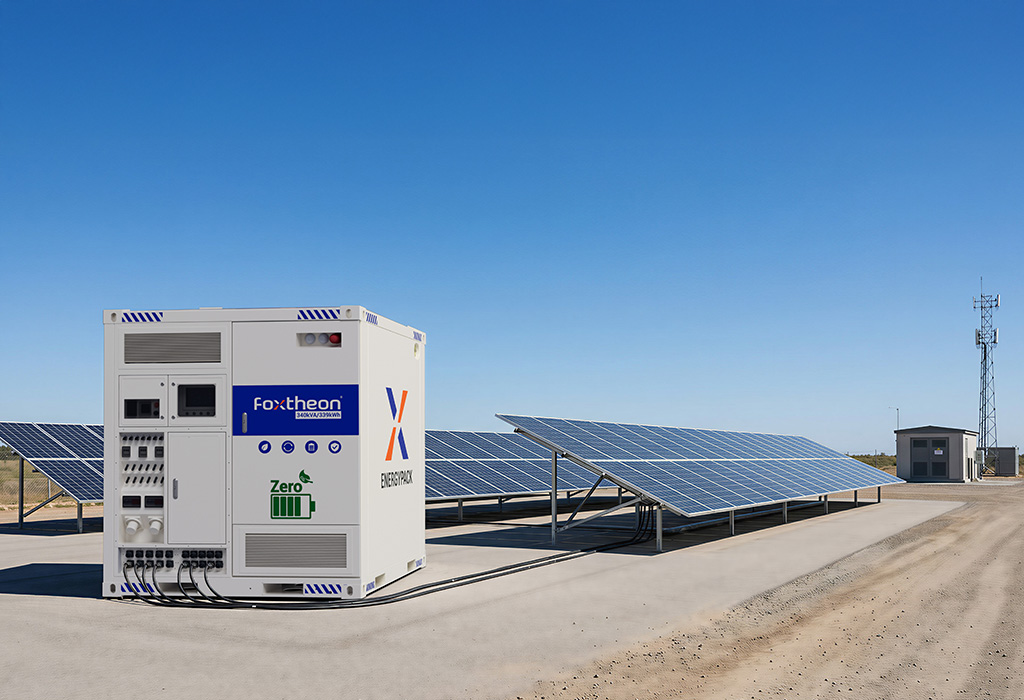
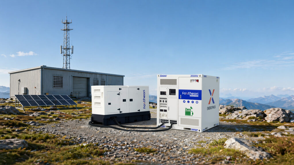
In remote industrial sites, mining operations, and facilities requiring high reliability, energy supply often relies on hybrid microgrids. Implementing a battery energy system alongside traditional reciprocating diesel or gas generators offers significant operational advantages. Rather than seeking to replace these reliable generator assets, the storage system functions as a dynamic companion.
Generators operate most efficiently within specific load ranges, typically between 60% and 80% of their rated capacity. Low-load operation, often called “wet stacking” in diesel engines, leads to incomplete combustion and accelerated maintenance requirements. By integrating a storage system, the battery can absorb load fluctuations and act as a “spinning reserve.” This allows generators to operate at constant, optimized loads, while the battery manages transient spikes and sudden drop-offs. Integrated hybrid solutions engineered by Foxtheon demonstrate how coordinating storage with existing generation assets improves overall fuel efficiency and reduces mechanical wear on internal combustion engines.
Material Considerations and Manufacturing Quality Standards
Enclosure Materials and Ingress Protection
The physical housing of a utility-scale or C&I storage system must withstand harsh environmental conditions while protecting the sensitive electronics and cells inside. High-quality enclosures are typically constructed from galvanized or stainless steel, coated with anti-corrosion marine-grade paint (C4 or C5-I classifications according to ISO 12944 standards).
Ingress Protection (IP) ratings are paramount for outdoor installations. Systems rated at IP54 or IP55 prevent the ingress of dust and protect internal components from rain and splashed water. For coastal or high-humidity regions, NEMA 3R or NEMA 4X enclosures are specified to prevent salt-spray damage and ensure long-term structural integrity. The internal racking must also be seismically rated (typically compliant with IEEE 693 or local building codes) to prevent displacement during geological events.
Thermal Control Systems
Maintaining a uniform temperature across all battery cells is a primary factor in preventing premature degradation and localized thermal issues. Two main thermal management designs are common in commercial installations:
- Forced Air Cooling: Utilizes fans and ducting to circulate conditioned air through the battery cabinets. While simpler and less costly to maintain, air cooling can result in temperature gradients between cells situated near the air inlet and those at the exhaust.
- Liquid Cooling: Employs a closed-loop coolant system with cold plates in direct contact with the battery cells or modules. Liquid cooling provides significantly higher heat transfer coefficients, maintaining temperature differentials across the entire pack within a tight range (typically under 2°C to 3°C). This precise control extends battery life and supports high-rate charge and discharge profiles.
In addition to active cooling, the structural shell of the battery energy system is often lined with thermal insulation panels to minimize the impact of external solar loading, ensuring the HVAC or liquid chilling units operate with optimal efficiency.
Strategic Procurement: Sourcing and Technical Specifications Evaluation
Defining Capacity Requirements and Duty Cycles
Specifying a battery energy system requires a detailed analysis of the facility’s load profile, ideally documented in 15-minute intervals over a full calendar year. Engineers must identify:
- Peak Power Requirements (kW): The maximum discharge rate required to meet transient loads or peak shaving targets.
- Energy Capacity Requirements (kWh): The total duration for which the peak power must be sustained.
- Expected Daily Cycles: Whether the system will perform one full cycle per day (e.g., peak shifting) or multiple micro-cycles (e.g., frequency regulation).
Understanding these parameters prevents system oversizing, which adds unnecessary weight and footprint, and undersizing, which accelerates degradation and fails to meet peak mitigation objectives.
Evaluating Supplier Capabilities and Engineering Integration
Sourcing a system involves looking beyond cell brands to evaluate the manufacturer’s integration expertise. A complete system consists of the battery modules, BMS, Power Conversion System (PCS) or inverter, and Energy Management System (EMS) software. Sourcing from a single integrated supplier simplifies commissioning and ensures compatibility between the communication protocols (such as Modbus TCP/IP, CAN bus, or DNP3).
Consulting with specialists such as Foxtheon helps system integrators match their local electrical codes with appropriate product certifications. Key global compliance standards include UL 9540 (for energy storage systems and equipment), UL 1973 (for batteries in stationary applications), and IEC 62619 (specifying safety requirements for secondary lithium cells and batteries in industrial applications). Testing under UL 9540A, which evaluates thermal runaway fire progression, is highly valuable for indoor installations or projects located close to property boundaries.
Frequently Asked Questions
Q1: What is the differences between LFP and NMC chemistries in industrial battery energy storage?
A1: Lithium Iron Phosphate (LFP) is widely favored in stationary applications due to its superior thermal stability, safety profile, and longer cycle life (often exceeding 5,000 cycles). Nickel Manganese Cobalt (NMC) features higher energy density, making it suitable for electric vehicles and space-constrained applications, but it exhibits lower thermal runaway thresholds and shorter overall cycle lives in comparison to LFP under similar operational profiles.
Q2: How does a battery management system (BMS) prevent thermal runaway?
A2: The BMS continuously monitors parameters such as individual cell voltage, current, and temperature. If a cell exhibits abnormal temperature rise or voltage drop, the BMS triggers alarms, curtails charge/discharge currents, or activates safety contactors to electrically isolate the affected battery string before thermal runaway can initiate or propagate.
Q3: Can a battery energy system be integrated with existing diesel generators?
A3: Yes. Storage systems can be integrated alongside diesel generators using hybrid controllers. The battery manages fast load transients and provides instantaneous power, allowing the generator to operate at its most efficient load point. This hybrid configuration reduces fuel consumption, prevents wet stacking, and reduces maintenance requirements on the generator.
Q4: What is the significance of the C-rate in commercial battery applications?
A4: The C-rate denotes the speed at which a battery is charged or discharged relative to its total capacity. A 1C rate means a 100 kWh system can deliver 100 kW of power for one hour. A 0.5C rate means the same system delivers 50 kW of power for two hours. Selecting the correct C-rate ensures the storage system matches the peak demand requirements of the target application.
Q5: Which international certifications are required for commercial deployment of battery energy systems?
A5: Primary international standards include UL 9540 (for the complete energy storage system), UL 1973 (for the battery modules), IEC 62619 (for industrial lithium batteries), and UL 9540A (for thermal runaway propagation testing). Compliance with these standards is typically required by local permitting authorities and electrical inspectors to ensure safety and grid interconnection compliance.
Technical Project Consultation & Inquiry
Designing a commercial energy storage project requires careful engineering and precise system sizing. To receive a detailed system proposal, engineering drawings, or technical specification sheets tailored to your facility, please compile your project parameters and contact our application engineering team.