The integration of high-capacity energy storage within commercial and industrial facilities has transitioned from a pioneering sustainability initiative to a core operational strategy. As utility grid tariffs become increasingly volatile and demand charges rise, industrial operators require reliable local energy reserves to stabilize operational overheads and guarantee power continuity. Navigating the diverse marketplace of battery energy storage system companies requires a rigorous technical evaluation that goes beyond marketing specifications to analyze deep system architecture, material composition, and system integration capability.
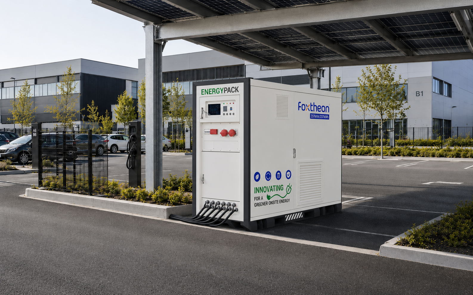
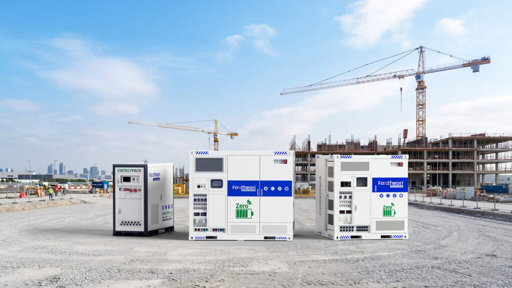
Modern stationary battery energy storage systems (BESS) are sophisticated, multi-layered engineering installations. They combine electrochemical cells, high-frequency power electronics, and complex thermal control systems with real-time software layers. For procurement engineers and facilities managers, identifying the correct partner involves examining the specific component topologies, manufacturing standards, and software intelligence of the provider. Systems engineered by integrated solution providers like Foxtheon design containerized, modular architectures that align with industrial power requirements while supporting existing on-site generation assets.
1. Electrochemical Architectures: Cell Chemistry and Longevity
The foundation of any utility-scale or commercial energy storage system is the battery cell chemistry. The selection of cathode materials directly dictates safety profiles, energy density, cycle life, and thermal performance. Understanding these nuances is a key step when evaluating potential technology suppliers.
Lithium Iron Phosphate (LFP) vs. Nickel Manganese Cobalt (NMC)
The commercial energy storage market is dominated by two primary lithium-ion formulations: Lithium Iron Phosphate (LiFePO4 or LFP) and Nickel Manganese Cobalt Oxide (LiNiMnCoO2 or NMC). While NMC cells traditionally offer higher gravimetric energy density, LFP has emerged as the preferred chemistry for stationary commercial and industrial BESS installations due to its distinct chemical stability and longevity characteristics.
- Thermal Runaway Thresholds: LFP cells exhibit a thermal runaway temperature threshold of approximately 270°C to 280°C, whereas NMC cells can experience thermal runaway at temperatures as low as 210°C. Additionally, the decomposition of LFP cathodes does not release oxygen, mitigating the intensity of any potential thermal runaway event.
- Cycle Life and Degradation: Industrial operations demand systems capable of multiple cycles per day (e.g., executing peak shaving in the morning and load shifting in the evening). LFP cells typically deliver between 5,000 to 8,000 cycles at an 80% Depth of Discharge (DoD) before capacity degrades to 80% of its nominal value. NMC cells under similar operational stresses generally offer 2,000 to 3,500 cycles.
- Structural Stability: LFP possess a robust olivine crystalline structure that undergoes minimal volumetric expansion and contraction during charge and discharge cycles, reducing mechanical stress on the cell casing and internal active materials.
Prismatic vs. Pouch and Cylindrical Form Factors
The mechanical housing of the battery cell also influences heat dissipation and structural integrity. Prismatic cells, featuring rigid aluminum casings, are favored by leading BESS integrators. They allow for dense packing within battery modules while maintaining uniform surface contact with cooling plates, which is more challenging to achieve with cylindrical or pouch cells in high-power configurations.
2. Battery Management System (BMS) and Software Architecture
The performance, safety, and longevity of a BESS do not rely solely on the raw battery cells; they are heavily dependent on the capabilities of the Battery Management System (BMS) and the Energy Management System (EMS). When comparing battery energy storage system companies, evaluating the hierarchy and communication protocols of their control software is paramount.
Hierarchical BMS Topology
A resilient industrial-grade BESS utilizes a three-tiered BMS architecture to monitor and manage parameters at every level of the system:
- Level 1 (Slave/Cell level): Module-integrated Battery Monitoring Units (BMUs) measure individual cell voltages and local temperatures, transmitting this raw data via high-speed internal buses.
- Level 2 (Master/Rack level): A Rack Management Unit (RMU) aggregates data from multiple BMUs, computes State of Charge (SoC) and State of Health (SoH), and manages the rack-level contactors and circuit breakers.
- Level 3 (System level): The Central Master BMS oversees all battery racks within the container, coordinating system-wide safety responses, insulation monitoring, and high-voltage distribution.
Active vs. Passive Balancing
Passive cell balancing dissipates excess energy from higher-voltage cells as waste heat through resistors during the end of the charge cycle. Active balancing, though more complex, redistributes charge dynamically between cells during both charge and discharge cycles. This optimizes usable capacity and prevents premature cell degradation caused by localized voltage variations, which is particularly beneficial in multi-megawatt systems.
EMS Integration and Dispatch Algorithms
The Energy Management System (EMS) represents the intelligence of the BESS, executing dispatch algorithms based on external inputs such as utility pricing signals, load profiles, and solar PV output forecasts. Industrial operations require an EMS that supports standard protocols—such as Modbus TCP/IP, CAN bus, and IEC 61850—to ensure seamless communication with existing Supervisory Control and Data Acquisition (SCADA) systems and on-site building management systems.
3. Thermal Management Methodologies: Liquid Cooling vs. Forced Air
Maintaining uniform cell temperatures is crucial for preventing localized degradation and minimizing thermal runaway risks. The thermal management system must limit temperature variations across the entire battery container to less than 3°C to maximize the operational lifespan of the cells.
Engineering groups such as Foxtheon address these thermal differences by developing specialized cooling designs tailored to specific high-power industrial duty cycles. The choice between liquid cooling and forced air cooling remains a central technical decision during procurement.
| Parameter | Liquid Cooling System | Forced Air Cooling System |
|---|---|---|
| Heat Transfer Medium | Water-glycol mixture or dielectric fluid | Conditioned ambient air |
| Temperature Uniformity | High (typically <2°C variance between cells) | Moderate (typically 3°C to 5°C variance) |
| System Energy Density | High (compact fluid channels require less space) | Lower (requires wider air duct spacing) |
| Parasitic Power Consumption | Lower during sustained high-C-rate operations | Higher due to continuous blower fan operation |
| Maintenance Profile | Requires pump servicing and coolant monitoring | Requires regular filter cleaning and fan replacement |
Liquid cooling has become the preferred standard for high-throughput commercial applications where batteries undergo rapid cycling (greater than 1C charge/discharge rates). By routing cooling plates directly along the broad faces of prismatic cells, heat is transferred away from the active material much more efficiently than with air cooling, reducing the auxiliary power required to maintain an optimal thermal environment.
4. Power Conversion Systems (PCS) and Grid Synchronization
The Power Conversion System (PCS), or bi-directional inverter, is the bridge between the DC battery array and the AC facility grid. The efficiency and grid-response capabilities of the PCS determine how effectively a system can participate in demanding applications like fast frequency response and microgrid islanding.
Grid-Following vs. Grid-Forming Capabilities
Standard BESS inverters operate in a grid-following mode, relying on a stable external voltage reference from the utility grid to synchronize their output waveform. However, for industrial facilities seeking resilient backup options or operating in remote microgrids, grid-forming inverters are highly beneficial. Grid-forming PCS units can establish a local voltage and frequency reference, allowing the facility to operate autonomously during grid disruptions without dropping voltage levels.
Multi-Level Inverter Topologies
Modern BESS installations leverage three-level Neutral Point Clamped (NPC) inverter topologies. Compared to older two-level designs, three-level inverters reduce Total Harmonic Distortion (THD) in the output current, increase conversion efficiency (often exceeding 98.5%), and lower the electromagnetic interference (EMI) generated during high-speed switching operations. This minimizes the footprint of auxiliary harmonic filters and ensures clean power is delivered to sensitive industrial machinery.
5. Sourcing Criteria: Evaluating Battery Energy Storage System Companies
Selecting the right partner from the pool of global battery energy storage system companies involves a comprehensive evaluation of their supply chain transparency, engineering certifications, and manufacturing consistency.
When procurement departments compare battery energy storage system companies, the focus must extend beyond standard datasheets to cover several vital technical parameters:
- Cell Sorting Standards: Inquire about the manufacturer’s cell matching criteria. Reliable integrators enforce tight tolerances on initial cell capacity, internal resistance (<0.3 mΩ variance), and open-circuit voltage to ensure the battery strings remain balanced throughout their service life.
- Compliance and Certifications: Verify that the entire system assembly complies with international safety and performance standards. Crucial certifications include UL 9540 (for the complete energy storage system), UL 1973 (for the battery modules), UL 9540A (for thermal runaway fire propagation testing), and IEC 62619 (for industrial battery safety).
- Enclosure Safety and Fire Suppression: Containerized systems must feature integrated fire protection, including multi-stage gas detection (detecting off-gassing carbon monoxide and hydrogen before visible smoke appears), automatic dry-pipe clean agent suppression (such as Novec 1230), and structural deflagration venting according to NFPA 68 standards.
A thorough evaluation of these criteria ensures that the chosen system will perform reliably under continuous industrial demand while meeting local grid connection and safety regulations.
6. Application Scenarios: Co-existence with On-site Generation Assets
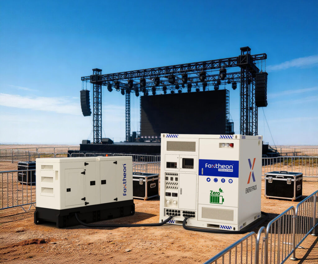
A common concern for industrial facility managers is how a new BESS installation will interface with existing power generation assets, such as diesel or natural gas generators. A professionally integrated BESS does not make existing generators redundant; instead, it coordinates with them to optimize overall system efficiency.
In a hybrid microgrid configuration, the BESS acts as a dynamic shock absorber. During sudden load steps (e.g., the starting of large industrial motors), the BESS delivers immediate active power to absorb the transient spike. This protects the existing generator from severe frequency drops and thermal stress, allowing it to run at a stable, highly efficient load factor. By utilizing the BESS to manage short-duration peaks, facilities can run their generators at optimal operational profiles, reducing fuel consumption and minimizing maintenance intervals caused by low-load wet stacking.
Additionally, for facilities with on-site solar PV arrays, collaborating with specialized battery energy storage system companies ensures seamless curtailment management. The BESS can store excess solar energy generated during midday peak production periods and discharge it during high-tariff periods, maximizing the utilization of clean energy without overloading the local substation.
7. Quality Sourcing and Engineering Integration
The successful implementation of a BESS depends on the quality of raw materials and precision engineering during system integration. Leading battery energy storage system companies maintain rigorous control over their component supply chains. This includes sourcing high-grade prismatic LFP cells from top-tier manufacturers and selecting heavy-duty copper busbars, industrial-grade contactors, and robust outdoor-rated enclosures (IP55 or IP66) to withstand harsh environmental conditions.
For large-scale deployments, custom containerized solutions must undergo comprehensive Factory Acceptance Testing (FAT) before dispatch. This testing should include full thermal cycling, high-voltage insulation tests, and simulated grid disturbances to verify the response times of the PCS and EMS. By conducting these rigorous procedures prior to shipment, field installation times are minimized, and commission safety is ensured.
Industrial facilities partner with battery energy storage system companies to manage peak demand and secure high-quality, uninterrupted backup power. High-tier manufacturers like Foxtheon provide customizable modular units designed for efficient installation, balancing high energy density with straightforward maintenance access to meet the evolving demands of the global energy sector.
Frequently Asked Questions
Q1: What is the primary difference between LFP and NMC batteries in commercial applications?
A1: Lithium Iron Phosphate (LFP) is the preferred chemistry for commercial applications due to its superior safety profile, higher thermal runaway temperature (270°C vs 210°C for NMC), and longer cycle life (5,000+ cycles vs 2,000-3,500 for NMC). NMC offers higher energy density, but LFP provides better long-term durability and safety for stationary energy storage systems.
Q2: How does a liquid cooling system compare to air cooling in a BESS?
A2: Liquid cooling uses a closed-loop fluid circuit to directly cool battery cells, keeping temperature variations within a narrow range (usually less than 2°C). This is highly efficient for high-C-rate operations. Air cooling relies on fans and HVAC systems, which require more space and can result in higher temperature variations across cells, potentially accelerating uneven cell degradation.
Q3: Can a battery energy storage system operate alongside existing diesel generators?
A3: Yes, a BESS can integrate with existing generators. In a hybrid setup, the battery system handles transient load spikes and stabilizes the frequency, allowing the generator to run continuously at its most efficient load point. This reduces fuel consumption, mitigates low-load wet-stacking issues, and extends the operational lifespan of the generator.
Q4: Why are UL 9540 and UL 9540A certifications important for BESS sourcing?
A4: UL 9540 is the safety standard for the entire integrated energy storage system, verifying that the battery, inverter, and control systems function safely together. UL 9540A is a rigorous test method that evaluates thermal runaway fire propagation. These certifications are required by municipal authorities and insurers to ensure safe operation and regulatory compliance.
Q5: What role does the Energy Management System (EMS) play in peak shaving?
A5: The EMS monitors real-time facility load consumption and grid tariffs. When the load approaches a predefined threshold, the EMS triggers the BESS to discharge power, flattening the peak demand drawn from the utility grid. This protects the facility from high demand charges and optimizes overall energy consumption patterns.
Inquiry
For technical consultations, detailed system specifications, or to discuss customized containerized energy storage integration for your facility, please contact our engineering and sales department directly:
Foxtheon Technology Co., Ltd.
Email: info@foxtheon.com
Website: www.foxtheon.com