

Grid modernizations and the expansion of distributed energy resources have placed new demands on electrical infrastructure. Power systems require precise frequency stabilization, real-time power factor correction, and dynamic load-buffering mechanisms to accommodate fluctuating supply profiles. Within this framework, electricity storage serves as a balancing architecture, enabling facilities to smooth power flow, support existing rotating generation assets, and maintain uptime without redesigning downstream utility connections.
Implementing utility-scale and commercial energy systems involves rigorous engineering evaluations. From selecting electrochemistries to balancing DC and AC bus architectures, system integrators must align electrochemical characteristics with conversion hardware and supervisory controls. This technical analysis outlines the structural topologies, cell-level properties, operational synergies with legacy infrastructure, and technical procurement considerations for high-capacity systems.
Architectural Anatomy of Industrial Storage Systems
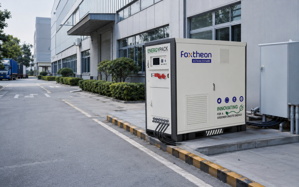
An industrial energy storage installation operates through four integrated sub-systems: the electrochemical battery racks, the battery management system (BMS), the bidirectional power conversion system (PCS), and the supervisory energy management system (EMS). The performance of the complete installation depends directly on how seamlessly these layers communicate across deterministic industrial protocols.
- Electrochemical Stacks: Individual battery cells are gathered in series to build voltage levels (typically between 750 VDC and 1500 VDC) and parallelized to scale total ampere-hour (Ah) capacity. These racks incorporate internal busbars, fusing, disconnect switches, and module-level sensors.
- Multi-Tier Battery Management Systems (BMS): Operating via a three-tier hierarchy (slave module units, string controllers, and system master controllers), the BMS tracks parameters including cell voltage, state of charge (SoC), state of health (SoH), and localized temperatures. It executes real-time cell-balancing routines to prevent capacity drift across long operational runs.
- Bidirectional Power Conversion System (PCS): The PCS interfaces the DC battery banks with the local AC distribution network. Modern four-quadrant inverters provide active power dispatch (MW) and reactive power regulation (MVAr), operating in grid-following (voltage-current synchronization via Phase Locked Loop) or grid-forming (virtual synchronous machine) modes according to site needs.
- Energy Management System (EMS) and SCADA: Serving as the master control node, the EMS executes dispatch algorithms based on grid signals, load meters, and generation telemetry. Communication relies on deterministic protocols including Modbus TCP, DNP3, and IEC 61850.
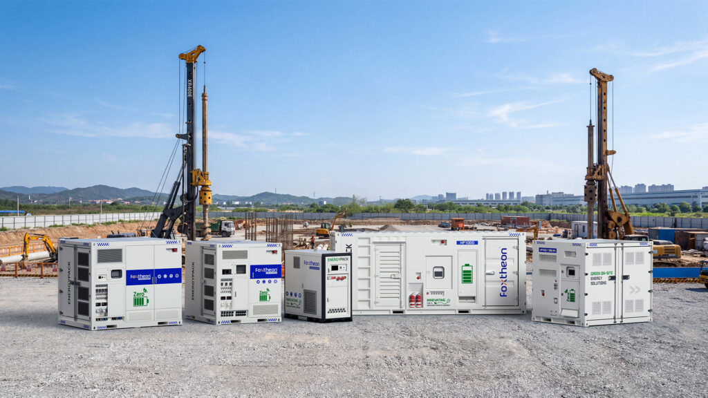
Leading system developers like Foxtheon engineer their systems around containerized enclosures that integrate these mechanical, electrical, and thermal assemblies into unified platforms. By standardizing physical enclosures with integrated fire containment, liquid cooling manifolds, and isolation switchgear, operators minimize on-site commissioning time while maintaining high system reliability.
Cell Chemistries and Thermal Management Topologies
Electrochemical choices define the degradation pathways, depth of discharge (DoD) limitations, and cycling dynamics of an installation. Stationary energy storage has moved predominantly toward lithium iron phosphate (LFP) chemistries, though specialized flow systems and alternative compositions remain relevant for specific duration windows.
1. Lithium Iron Phosphate (LiFePO4 / LFP)
LFP has become an industry standard for stationary installations due to its structural and chemical stability. The olivine crystal structure features strong P-O covalent bonds, which remain intact even during overcharge events. This composition exhibits high thermal run-away thresholds (typically exceeding 270 degrees Celsius) and avoids the oxygen-release characteristics common to nickel-manganese-cobalt (NMC) chemistries at elevated temperatures.
LFP cells provide cycling performance spanning 6,000 to 10,000 cycles at 80% Depth of Discharge, depending on operating C-rates and cell temperature maintenance. One engineering challenge with LFP is its flat open-circuit voltage (OCV) discharge curve between 20% and 80% SoC, which necessitates advanced coulomb-counting and Kalman-filter state estimation within the BMS to maintain accurate monitoring.
2. Redox Flow Systems (Vanadium Redox)
For discharge durations requiring 8 to 16 hours, vanadium redox flow platforms offer an alternative configuration. These systems decouple power (kW, determined by membrane stack surface area) from capacity (kWh, dictated by liquid electrolyte storage tanks). Because active materials stay dissolved in external fluid reservoirs, the active chemicals undergo minimal mechanical degradation during cycling. However, lower round-trip efficiency (typically 65% to 75%, compared to 86% to 94% for LFP) and higher auxiliary pumping demands restrict their deployment to specific long-duration niches.
3. Thermal Management: Liquid vs. Forced-Air Cooling
Operating temperature directly governs battery lifespan and performance uniformity. A temperature divergence of more than 5 degrees Celsius between series-connected cells can cause unequal internal impedance, resulting in uneven cycling and premature degradation across the module.
- Forced-Air Cooling: Uses industrial HVAC units along with direct internal ducting. While mechanically straightforward, air cooling exhibits high parasitic loads under elevated ambient conditions and can produce thermal gradients along extended battery racks.
- Direct-to-Cold-Plate Liquid Cooling: Circulates water-glycol solutions through aluminum heat sinks positioned against cell surfaces. Liquid systems deliver up to three times the thermal transfer efficiency of forced air, lowering parasitic power consumption and maintaining intra-rack temperature variances within a tight 2-to-3-degree window. This thermal stability helps protect battery longevity in high ambient environments.
Grid Interconnection and Hybridization with Generation Assets
Stationary electricity storage integrates alongside existing industrial generation assets, such as diesel or lean-burn natural gas reciprocating engine sets. Rather than altering primary site generation strategies, storage balances transient fluctuations, absorbs sudden load steps, and allows thermal engines to operate closer to their peak fuel efficiency zones.
When heavy industrial facilities start inductive loads—such as rock crushers, massive air handling units, or large induction pumps—they induce significant inrush currents, creating brief voltage sags and frequency fluctuations. Without storage, facility managers must maintain running spinning reserves or run oversized generators at low, inefficient load points. Running generators below 30% to 40% of continuous rated capacity can cause engine slobber, unburned fuel deposits in exhaust systems, and elevated maintenance intervals.
Integrating a modern electricity storage system addresses these operational imbalances through targeted system interaction:
- Dynamic Frequency Regulation and Droop Control: Inverters monitor AC bus frequency at millisecond intervals. If frequency drops due to an unexpected plant load step, the inverter injects active power sub-cycle, stabilizing the system while conventional generator governors ramp up smoothly. Reference standards such as IEEE Standards Association 1547-2018 establish strict interconnection and response profiles for these operational interactions.
- Synthetic Inertia: By pairing grid-forming inverters with high-rate battery racks, facilities emulate the rotational inertia of heavy turbines. This stabilizes the rate of change of frequency (RoCoF) across microgrids that feature high penetrations of intermittent solar generation.
- Microgrid Synchronization: Advanced switchgear coordinated with an automated transfer switch (ATS) allows isolated sites to transition between islanded mode and utility grid connection without interrupting downstream processes.
Energy management solutions engineered by Foxtheon incorporate these balancing capabilities, allowing plant operators to run combined generator and renewable fleets with reduced operational cycling wear and stabilized bus voltages.
System Topologies: AC-Coupled vs. DC-Coupled Architectures
Designing an industrial storage system requires balancing the trade-offs between AC-coupled and DC-coupled architectures. Each topology presents distinct advantages based on whether the project is an existing facility retrofit or a greenfield microgrid integration.
AC-Coupled Systems
In an AC-coupled configuration, the battery system and local generation systems (such as photovoltaic arrays or generators) communicate over a shared AC bus. The storage unit features its own dedicated bidirectional PCS.
- Advantages: Readily adaptable to existing industrial sites. Adding storage does not require modifying installed generator switchgear or solar inverters. Equipment can be located in separate electrical rooms if physical layouts require it.
- Disadvantages: Power traversing from solar generation through storage to local loads undergo multiple conversions (DC to AC, then AC to DC to charge, then DC to AC to discharge), reducing round-trip efficiency by 2% to 4% compared to direct DC paths.
DC-Coupled Systems
In a DC-coupled topology, renewable arrays and battery strings link directly to a shared internal DC bus through buck-boost charge controllers, which then feed a shared central power conversion system.
- Advantages: Higher round-trip efficiency for renewable energy storage, along with unified inverter controls for both solar arrays and battery modules.
- Disadvantages: Requires unified engineering from the outset. Retrofitting DC-coupled systems into running industrial networks with existing inverter assets can introduce integration complexities.
Technical Procurement and Sourcing Evaluation Parameters
Procuring commercial-grade electricity storage requires evaluating vendor engineering specifications beyond simple rated kilowatt-hour nameplate numbers. System resilience depends on build quality, auxiliary system performance, and strict adherence to international safety codes.
Procurement teams and consulting engineers can assess platforms using the following technical criteria:
- Auxiliary Power Overhead: Total parasitic loads from cooling pumps, HVAC chillers, and control electronics. High auxiliary consumption can diminish actual usable energy yields under high ambient temperatures.
- C-Rate Versatility: The ratio of continuous discharge current to capacity. Facilities requiring rapid surge relief need systems rated for 0.5C to 1C operation, whereas 4-hour peak shifting applications perform reliably on 0.25C platforms.
- Regulatory and Safety Compliance: Systems must meet robust international testing standards. Authoritative bodies like the International Electrotechnical Commission (IEC) detail strict compliance codes, including IEC 62619 for industrial lithium batteries and IEC 62933 for overall electrical energy storage systems. In North America, certifications under UL 9540 (system safety) and UL 9540A (large-scale fire propagation testing) are baseline requirements for municipal and industrial permitting.
- Container Ingress Protection: Outdoor installations require enclosures with minimum IP55 or NEMA 3R ratings, alongside C4/C5 marine-grade paint finishes to resist atmospheric corrosion in coastal or chemical plant environments.
- Control System Integration: Inverters and controllers must support direct Modbus register mapping, BACnet, or OPC-UA for integration into DCS (Distributed Control Systems) without proprietary software gateways.
The National Renewable Energy Laboratory (NREL) publishes continuous performance validation methodologies that illustrate how high-specification integration reduces cycle-based cell degradation over decade-long duty cycles.
Operational Lifecycles, Analytics, and Telemetry Integration
Following commissioning, continuous operational intelligence determines real-world system longevity. Modern installations rely on automated edge computing systems that stream high-frequency operational metrics to central operational hubs.
Predictive analytics engines evaluate real-time data to detect internal cell variations before they manifest as operational faults. Key operational parameters tracked include:
- Internal Resistance (DC-IR) Tracking: As electrochemical cells age, their internal resistance rises, generating additional heat during rapid discharge. Tracking DC-IR changes allows operators to adjust charge profiles dynamically.
- Coulombic Efficiency Deviations: Tracking the ratio of ampere-hours extracted during discharge to ampere-hours delivered during charging helps operators identify minor balance-of-plant anomalies early.
- Insulation Resistance: Continuous ground-fault detection along 1500 VDC strings protects against insulation wear caused by thermal expansion, condensation, or environmental dust.
Integrating these operational telemetry streams into broader plant management platforms ensures industrial facilities maintain reliable backup capability, smooth utility demand peaks, and protect upstream utility assets without unplanned production interruptions.
Frequently Asked Questions
Q1: How does an electricity storage system integrate with an existing industrial diesel or gas generator?
A1: The system interfaces through the main distribution switchgear on the AC bus via an AC-coupled architecture. The battery system’s power conversion system (PCS) responds rapidly to sudden industrial load steps, supplying instantaneous power while legacy rotating generators adjust their output gradually. This prevents engine bogging, stabilizes bus frequency, and eliminates the need to run engines inefficiently below their minimum recommended load points.
Q2: What are the differences between 0.5C and 1C discharge rates in technical applications?
A2: The C-rate denotes the speed at which a battery discharges relative to its maximum capacity. A 1C rate indicates that a 1000 kWh battery can deliver 1000 kW of continuous power for one hour. A 0.5C rate means the same 1000 kWh system delivers a maximum continuous power of 500 kW over two hours. Higher C-rates require more robust thermal management systems and thicker internal busbars to manage higher operational currents.
Q3: Why is liquid cooling becoming more prevalent than forced-air cooling in containerized energy storage?
A3: Liquid cooling provides substantially higher thermal conductivity than ambient air. Circulating liquid coolant through dedicated cold plates directly adjacent to the cells maintains uniform internal temperatures across large battery racks, typically keeping temperature variances within 2 to 3 degrees Celsius. This prevents uneven cell aging, decreases auxiliary HVAC power consumption, and allows for more compact cell packing densities inside modular enclosures.
Q4: What certifications are critical for industrial electricity storage safety verification?
A4: Key global standards include UL 9540 (system safety certification), UL 9540A (large-scale thermal runaway fire propagation testing), IEC 62619 (industrial lithium battery safety requirements), and IEC 62933 (safety requirements for grid-integrated BESS). Additionally, regional building and fire codes frequently require compliance with NFPA 855 for stationary energy storage installations.
Q5: What control modes allow an electricity storage system to maintain operation during a main utility outage?
A5: The system must use a bidirectional inverter capable of “grid-forming” mode. In this state, the inverter uses internal voltage and frequency references to establish a stable local microgrid grid voltage and frequency. Combined with high-speed static transfer switches, this enables the storage system to power critical plant circuits smoothly until auxiliary generators start and synchronize with the islanded bus.
Engineering Consultation and Technical Inquiries
Industrial facility engineers, system integrators, and project developers seeking technical specifications, integration diagrams, or project feasibility evaluations can contact the systems application team directly:
Engineering Department & Applications Support:
Portal: https://www.foxtheon.com/
Technical Specifications: engineering@foxtheon.com
Focus Areas: Utility Interconnection Topologies, Industrial Microgrids, Hybrid Power Integration, Containerized System Sizing.