How to Size a Battery Energy Storage System for an Off-Grid Project

Table of Contents

Practical BESS sizing guide

BESS sizing for off-grid projects should treat power and energy as separate requirements.

Use measured time-series data to size PCS power in kW and kVA, calculate usable kWh between charging windows, and verify recharge headroom, reserve, derating, protection and site constraints.

PowerContinuous kW, kVA and current
EnergyUsable kWh between charges
RechargeSource headroom and recovery time
ReserveNext event and contingency margin

A battery can have enough kWh for a full shift and still trip if the PCS cannot carry a motor start. The reverse is also true: a high-power unit can cover a short peak but run out of energy during a quiet-power window. The practical result is a power-and-energy envelope, not one capacity number.

BESS sizing for off-grid projects at a glance

Sizing checkInputsWhat it determines
Continuous powerCoincident site kW, kVA and currentPCS continuous rating and source contribution
Short peakPeak magnitude, duration, repetition and power factorPCS overload curve and protection settings
Usable energyTime-series discharge between effective chargesBattery kWh within the permitted state-of-charge window
RechargeSource headroom, charge limit and available timeRecovery time and generator or grid operating schedule
ReserveNext required event, contingency policy and aging allowanceMinimum state of charge and installed energy margin
Site fitTemperature, altitude, access, lifting, cables and approvalsDerating, enclosure, logistics and connection design

Step 1: Measure the load at the right resolution

Start with measurements at the site’s point of connection. Record active power, apparent power, current, voltage, frequency and power factor together with the operating sequence. A connected-load list is useful for an initial review, but it cannot show which machines operate together or how long a start or lift lasts.

The sample interval must be shorter than the event the BESS is meant to support. A one-minute average can hide a ten-second crane, pump or crusher peak. Keep the raw fast-event data and a longer profile covering the full shift, day or operating cycle. Starting current also depends on the motor, variable-frequency drive or soft starter, so do not apply one generic multiplier to every machine.

Step 2: Define the source and operating duty

Define what the grid, generator and solar system will contribute before choosing the battery. The same site load can produce very different BESS requirements depending on whether the battery only clips peaks, runs the site during quiet hours or forms an islanded microgrid.

  • State the maximum permitted grid or generator contribution in both kW and kVA.
  • Identify periods when the source must be off and the battery must carry the complete coincident load.
  • Mark every dependable charging window and any periods when solar output may be unavailable.
  • Define the minimum reserve for the next planned peak, source failure or emergency shutdown.
  • Confirm whether grid export is prohibited and what connection approval is required.

Step 3: Calculate continuous and short-duration power

When the upstream source supplies a planned contribution, the preliminary battery active-power requirement at each time step is the positive difference between site demand and allowed source power.

PBESS(t) = max[Pload(t) − Psource(t), 0]

Use the maximum value in that series as the first active-power check. Repeat the check for kVA and current because low power factor or a fast transient can reach an inverter, cable or protection limit before the kW limit. If the BESS must run the site in island mode, the source term becomes zero and the PCS must carry the complete coincident load.

Match each event to the manufacturer’s continuous and short-duration overload curve. A headline peak rating is useful only when its stated duration covers the event and the battery can repeat that event without reaching a current, temperature or state-of-charge limit.

Step 4: Calculate usable battery energy

Battery energy is the accumulated discharge between effective charging opportunities. Calculate it from the time-series power deficit rather than from a daily energy total that mixes charging and discharging periods.

Edelivered = Σ[PBESS(t) × Δt]

Enominal ≥ (Edelivered + Eauxiliary + Ereserve) ÷ (efficiency × usable SoC fraction)

Use approved project values for conversion efficiency, auxiliary demand and the permitted state-of-charge window. Then check temperature limits, battery aging, maintenance policy and the response required if a charging opportunity is missed. Do not copy a fixed reserve percentage from another project; define reserve from the next required duty and the agreed contingency.

Worked example: separating power and energy

Consider an illustrative site with an 80 kW upstream-source limit, a 50 kW steady load and a 140 kW peak lasting 20 seconds. The BESS must provide at least 60 kW of active power during the peak, subject to separate kVA, current and protection checks. That 20-second event uses only 0.33 kWh, showing why the peak sets power but may add little energy.

Peak energy = 60 kW × 20 ÷ 3,600 = 0.33 kWh

Now assume the battery must also supply a 25 kW average load for a four-hour quiet period. It must deliver 100 kWh. With an illustrative 80% usable state-of-charge window and 90% system efficiency, the base nominal capacity is 138.9 kWh before auxiliary demand, reserve, aging and temperature allowances.

Base nominal energy = 25 kW × 4 h ÷ (0.80 × 0.90) = 138.9 kWh

With the site back at 50 kW, the 80 kW source leaves 30 kW of ideal charging headroom. Replacing 100 kWh at 90% charge efficiency takes about 3.7 hours before charge tapering or other limits. If the dependable charging window is shorter, adding battery kWh alone does not solve the operating cycle; the source headroom, charge rate or dispatch schedule must change.

Minimum ideal recharge time = 100 kWh ÷ (30 kW × 0.90) = 3.7 h

Step 5: Verify recharge and state-of-charge recovery

At every time step, available charging power is limited by the source output left after the live load is served. It is also constrained by the PCS, battery, cables, generator and grid connection.

Pcharge available(t) = Psource allowed(t) − Psite(t)

Run a time-step simulation across the full duty cycle. Track source on/off state, battery charge and discharge power, state of charge, generator starts, solar production, losses and any unsupported load. Test credible adverse cases such as a longer shift, repeated peaks, a missed solar day, delayed fuel delivery or a reduced source limit. The simulation should show that the battery reaches its required reserve before the next critical event.

Step 6: Check site fit and product direction

Electrical sizing is only part of the selection. Confirm transport dimensions and weight, road and crane access, lifting points, ground-bearing capacity, cable route and length, ventilation clearances, flood exposure and protection against falling objects. Check rated voltage and frequency, earthing, protection coordination, grid-export controls and the destination market’s connection and fire-safety requirements. Temperature and altitude may reduce available power or energy and must be reviewed against the selected model’s current data sheet.

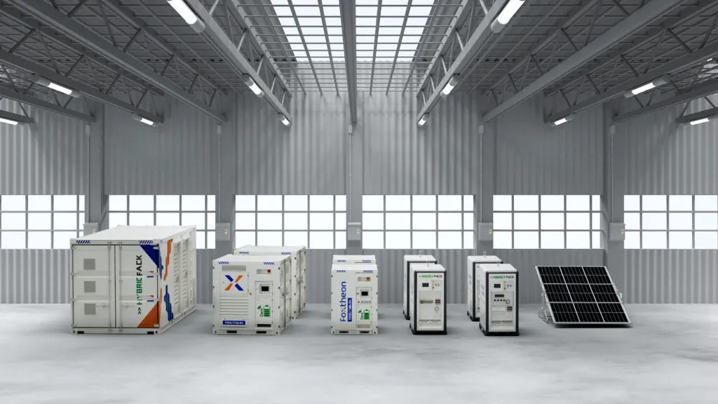
Within the Foxtheon EnergyPack hybrid BESS range, the first product-family decision follows the load profile. Use current product data and the technical agreement for final ratings and model selection.

Duty profileSelection priorityInitial EnergyPack direction
Short, steep industrial peaksPCS continuous rating, kVA, current and overload durationP Series as the first range to evaluate
Long quiet or off-grid periodsUsable kWh, cycle strategy, efficiency and thermal performanceM Series as the first range to evaluate
Mixed peak and long-duration dutyPower, energy and recharge simulation across the full cycleCompare both families and any parallel configuration

Step 7: Confirm compliance and project economics

Verify certification and compliance against the exact product configuration and delivery country. Requirements can differ for transport, battery safety, complete-system electrical safety, grid connection, fire protection and emissions from any paired generator. Do not assume that a certificate listed for one model or market applies to every system.

Calculate savings from the proposed dispatch, not from a universal percentage. Compare the baseline and hybrid cases using the generator fuel curve, delivered fuel price, grid tariff, generator operating hours and starts, maintenance, battery losses and degradation, transport, installation and any cost of downtime or a delayed grid upgrade. A larger battery may reduce runtime but can still weaken the business case if its additional energy is rarely used.

Field evidence from a grid-constrained construction site

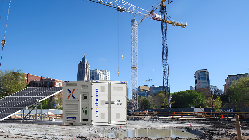
At a Foxtheon project in Malaysia, three tower cranes operated behind a 110 kW utility limit while recorded site demand reached 180 kW. The EnergyPack P350 supplied 40–70 kW during lifting peaks and kept grid draw within the utility limit. This field result illustrates the power-deficit calculation. It is not a universal battery-size ratio: peak duration, repeated crane cycles, recharge power, losses and reserve still determine the required kWh.

For a closer look at this operating mode, see Foxtheon’s weak-grid and utility-capacity expansion solution.

Data needed for a first sizing review

  • ✓ Time-series kW, kVA, current, voltage, frequency and power factor at the point of connection
  • ✓ Sample interval and the duration and repetition of the fastest important event
  • ✓ Operating hours, shift pattern, quiet periods and equipment sequence
  • ✓ Grid limit or generator model, rating, fuel curve and approved operating guidance
  • ✓ Motor starting method, variable-frequency drive settings and equipment manufacturer data
  • ✓ Solar contribution and its seasonal or weather-dependent limits
  • ✓ Required reserve, critical-load policy and response to a missed charging window
  • ✓ Temperature, altitude, access, enclosure, lifting, cable and ground-loading requirements
  • ✓ Protection, earthing, export control, fire-safety and point-of-connection requirements

Frequently asked questions

Should BESS sizing start with kW or kWh?

Start with coincident kW, kVA and current. Confirm that the PCS can carry the required continuous load and each short-duration event. Then calculate usable kWh between dependable charging opportunities.

How much battery reserve is needed?

Reserve depends on the next required peak, the agreed failure response, the operating policy and the product limits. Define it as a project requirement instead of applying a generic percentage.

Can a BESS allow a smaller generator?

Yes, when the battery and PCS supply the short power gap and the generator carries the planned sustained load plus charging. The load profile, overload curve and state-of-charge recovery study must confirm the design.

Can nameplate data replace site measurements?

Nameplates support preliminary work, but final selection should use measured or defensible modelled time-series data. Nameplates do not show coincidence, transient duration or recharge opportunities.

What is the most common BESS sizing mistake?

The most common mistake is choosing battery kWh before checking PCS power and recharge. A large energy capacity cannot compensate for an undersized inverter, and neither one solves a missing charging window.

Request a project sizing review

Send Foxtheon your load profile, source limits, operating schedule and site conditions. We can review the power-and-energy envelope, recommend an EnergyPack configuration and model the operating and cost assumptions for your project.

Request a technical consultation →

Can’t find what you are looking for?

Get A Quote