
Engineering guide · News blog
Tower crane BESS sizing starts with measured load data. Use it to calculate PCS power, usable battery capacity and recharge margin.
The short answer
Start with a time-series load profile measured at the crane feeder or site point of connection. Find the highest coincident demand and subtract the power that the grid or generator can safely provide. The difference is the load the BESS power conversion system must carry. Check it in both kW and kVA, and match the event to the PCS overload duration.Next, calculate the accumulated energy deficit between recharge opportunities. That gives the minimum usable battery capacity. A full-shift simulation should then confirm state of charge, recharge time, voltage and frequency behavior, temperature derating, protection settings and any regenerative power from the crane drives.| Rating or function | The question it answers |
|---|---|
| kW and kVA | Can the BESS support the lift without reaching its power or current limit? |
| Usable kWh | How many peaks can it cover before recharge is required? |
| Energy management system | When should the grid, generator and battery each contribute power? |
Why crane nameplate power is not enough
A crane data sheet may show the rated power of the hoist motor. That number does not describe the complete load at the site supply. Trolley and slewing drives also draw power, and the same connection may serve site hoists, pumps, welders, lighting and welfare facilities. Some of these loads overlap. Others can be sequenced.Starting method changes the result. Caterpillar notes that an electric motor can draw two to eight times its normal running current while starting. That range is relevant to direct-on-line motors, but it should not be copied into a calculation for a modern VFD-controlled crane. A variable frequency drive controls acceleration and speed, so the supply sees a different demand profile. Engineers still need to check input current, ramp rate, harmonics and regenerative behavior.Cummins’ generator application guidance models running and starting requirements by load step. It notes that a VFD gives the designer more control over the rate of load application, but the drive can remain sensitive to voltage variation. Measured feeder data and the crane drive documentation are therefore more useful than a generic starting-current multiplier.Step 1: build a usable load profile
Measure real power, apparent power, current, voltage, power factor and frequency. The sampling rate must be fast enough to capture the lifting events that the BESS will support. One-minute averages can hide a ten-second peak.Record several representative operating conditions:- the heaviest planned lift;
- hoist, trolley and slewing operation at the same time;
- two or more cranes operating concurrently;
- other site equipment switching on during a lift;
- lowering or braking events that may return energy;
- shift start, breaks and low-load recharge periods.
Step 2: calculate the power deficit
For a grid-constrained site, the active-power deficit at each time step is:P_bess(t) = max[P_load(t) - P_grid_limit, 0]For a generator hybrid, replace the grid limit with the generator power assigned to the load by the control strategy. Do not assume this equals the generator nameplate rating. Site derating, the emissions configuration, acceptable load steps, battery charging demand and the chosen operating point all affect the available contribution.The highest value of
P_bess(t) is the minimum active-power requirement before design reserve. Apparent power must be checked as well:S = √(P² + Q²)Here,
P is active power in kW, Q is reactive power in kvar, and S is apparent power in kVA.For a balanced three-phase system, current and apparent power are related by:S (kVA) = √3 × V × I ÷ 1000In this equation,
V is the line-to-line RMS voltage in volts and I is the line current in amperes.A PCS can reach its current or kVA limit while the measured kW still looks acceptable. Compare the load profile with the continuous rating and each short-duration overload rating, including the 10-second and 60-second limits where applicable.CLP Power’s construction-site BESS guideline uses the sum of coincident peak currents as an initial check. Final sizing still needs power factor, voltage dip, controls, protection and peak duration.Step 3: calculate usable energy separately from nameplate capacity
Power is the maximum gap the BESS must fill. Energy is the accumulated gap over time.For each interval, calculate the energy discharged above the source limit:E_deficit = Σ[max(P_load - P_source, 0) × Δt] ÷ η_dischargeBase the usable capacity on the largest cumulative energy deficit before the battery can recover. Then account for the permitted state-of-charge window, temperature, conversion losses, battery ageing and the project’s operating reserve.One peak is not enough to size the battery. Repeated crane cycles can lower state of charge across a shift even when each event lasts only seconds. Include charging during the valleys:
P_charge_available(t) = max[P_source_limit - P_load(t), 0]If the battery receives less energy between lifts than it supplies during the peaks, its state of charge will continue to fall. The design must then provide more source power, more usable battery capacity, a different operating sequence or a dedicated charging window.
What the Malaysia project shows
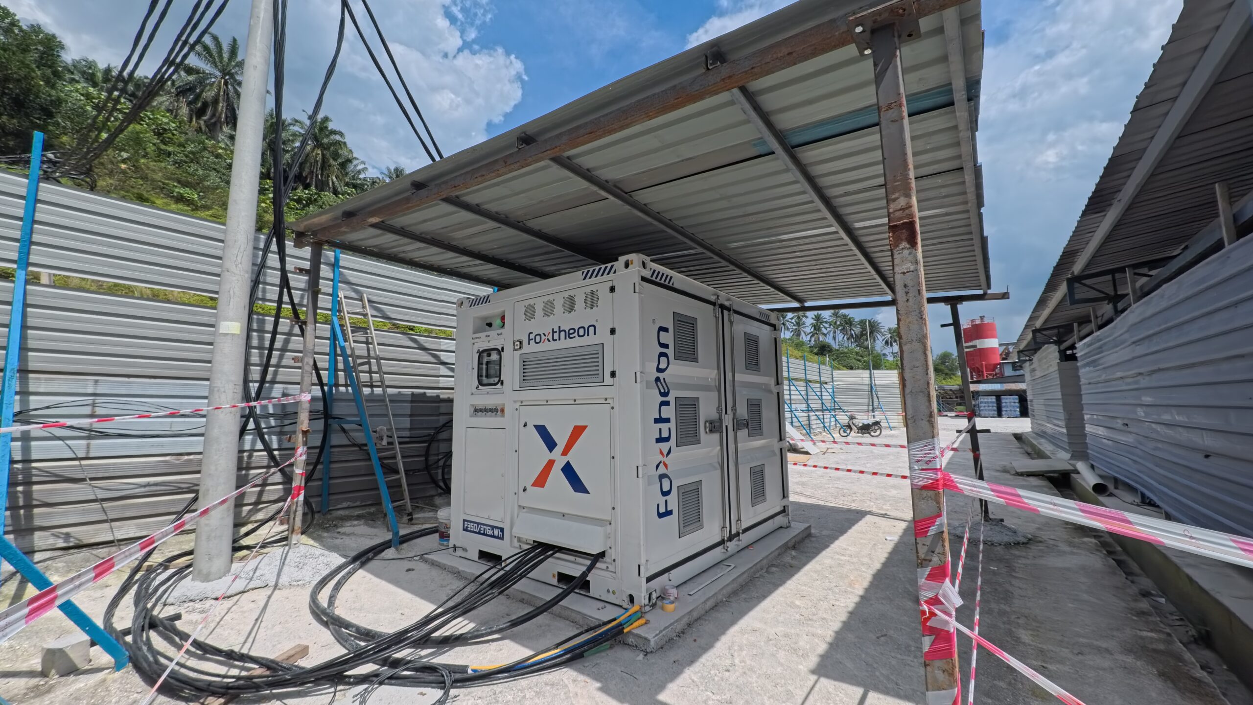
At a Malaysian infrastructure site, three tower cranes operated behind a utility connection limited to 110 kW. Site demand reached 180 kW. During peak events, the Foxtheon P350 supplied between 40 kW and 70 kW.At the maximum recorded demand, the active-power calculation is direct:180 kW site demand - 110 kW grid limit = 70 kW BESS contributionThe result is the maximum measured active-power deficit. It is not the complete system size. The design must still account for apparent power, peak duration, repeated cycles, charging time and operating reserve.Suppose that a 70 kW deficit accumulated for ten minutes before the next effective recharge period. The BESS would deliver:
70 kW × 10/60 h = 11.7 kWhThe 11.7 kWh figure applies only to this assumed interval. It is neither a product recommendation nor the project’s actual daily energy result. Capacity selection still requires a full-shift state-of-charge simulation.The deployed P350 has 376 kWh of battery capacity and worked as the energy buffer and site microgrid controller. The project reported that grid draw remained within the 110 kW limit while the three cranes operated. The 70 kW figure describes the largest reported power gap. Battery capacity and the control strategy determine whether the system can repeat that support through the working day.
Step 4: size the grid or generator contribution
The upstream source supplies the load below the control limit and recharges the energy discharged by the BESS.For a weak-grid project, check:- the contractual or protective limit at the point of connection;
- the maximum charging current allowed without causing a trip;
- other site loads sharing the same connection;
- import and export rules;
- the recharge time available between crane cycles and shifts.
- continuous site demand plus the planned battery charging power;
- the largest remaining load step after the BESS responds;
- acceptable voltage and frequency dip;
- minimum and preferred loading stated by the generator manufacturer;
- ambient temperature and altitude derating;
- start, stop and minimum-run-time logic;
- fuel, noise and emissions constraints.
Step 5: check the electrical details that a kW calculation misses
A preliminary kW and kWh calculation cannot confirm safe operation. Before procurement, review these points with the crane OEM, BESS supplier and project electrical engineer:| Check | Why it affects sizing |
|---|---|
| PCS continuous kW and kVA | Sets the sustained active and apparent power available |
| PCS overload curve | Confirms how much power is available for 1 s, 10 s, 60 s or longer |
| VFD input and DC-link behavior | Affects current ramps, harmonics and regenerative energy |
| Voltage and frequency limits | Prevents crane drives or protection devices from tripping |
| Short-circuit contribution | Affects protection coordination and fault clearing |
| State-of-charge reserve | Keeps headroom for the next lift or a source outage |
| Charge power and source limit | Determines whether the battery recovers during the shift |
| Ambient temperature and altitude | Can derate the PCS, battery and generator |
| Cable length and transformer impedance | Affect voltage drop and transient response |
| Grounding, earthing and protection | Must match local rules and the site’s operating mode |
A practical tower crane BESS sizing workflow
For a preliminary design review:- Collect high-resolution load data at the intended connection point.
- Define the source limit and the loads that may operate together.
- Calculate the maximum kW, kVA and current deficit.
- Match each peak to the PCS overload curve and response time.
- Integrate the deficit over time to calculate usable energy.
- Simulate charging and state of charge across the full shift.
- Apply documented derating, ageing allowance and project reserve.
- Check voltage, frequency, harmonics, fault current and protection.
- Validate the model with commissioning tests under controlled loads.
- Review operating data after deployment and tune the EMS limits.