
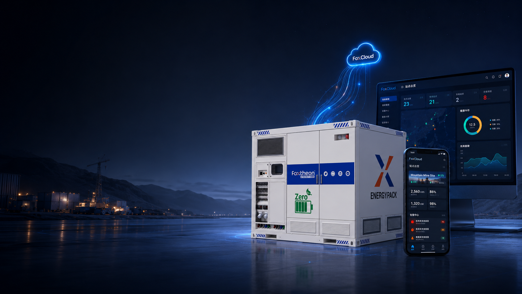
Modern electrical grids and industrial facility infrastructures are experiencing unprecedented shifts in load dynamics, power quality requirements, and operational continuity standards. To maintain voltage stability, mitigate peak demand charges, and integrate variable renewable energy resources, engineering teams increasingly rely on advanced energy storage technologies. Implementing a enterprise-grade li ion battery storage system provides the sub-second response times, precise power dispatch, and modular scalability required for complex power systems.
As smart energy solutions continue to evolve, companies such as Foxtheon are engineering containerized and modular energy storage architectures designed to interface seamlessly with existing distribution networks and on-site generation assets. Understanding the deep technical parameters of these installations—ranging from cell-level electrochemistry to system-level microgrid control protocols—is necessary for specifying resilient, compliant, and highly performant energy infrastructure.
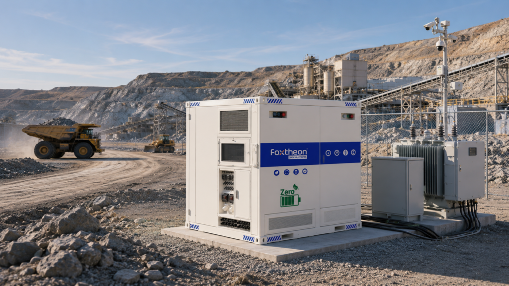
Electrochemical Cell Architectures and Material Selection
The core energy density, cycle durability, and thermal profile of a modern stationary energy storage facility are directly dictated by its underlying electrochemical cell selection. Industrial energy storage applications predominantly leverage Lithium Iron Phosphate (LiFePO4 or LFP) and Nickel Manganese Cobalt (NMC) chemistries, each offering distinct performance characteristics suited for specific operational profiles.
Lithium Iron Phosphate (LFP) Characteristics
LFP chemistry has become the industry standard for stationary industrial energy storage installations. The chemical structure of $LiFePO_4$ features strong covalent iron-oxygen-phosphorus bonds, which maintain structural stability under thermal and operational stress. Key technical attributes include:
- Nominal Cell Voltage: 3.2 V per cell.
- Cycle Durability: Exceeds 6,000 to 8,000 cycles at 80% Depth of Discharge (DoD) before reaching end-of-life (EOL) capacity thresholds (70% remaining capacity).
- Thermal Stability: High thermal runaway onset temperature (approximately 270°C), making it intrinsically resistant to structural oxidation during high-load charge and discharge cycles.
- C-Rate Capability: Capable of continuous operational rates from 0.5C to 1C, with continuous discharge capabilities aligned with long-duration energy storage demands.
Nickel Manganese Cobalt (NMC) Characteristics
NMC chemistries offer higher gravimetric and volumetric energy densities compared to LFP cells, making them relevant where spatial footprint constraints dominate engineering parameters. Key performance metrics include:
- Nominal Cell Voltage: 3.6 V to 3.7 V per cell.
- Energy Density: Ranging between 200 Wh/kg and 250 Wh/kg, allowing for compact enclosures.
- Cycle Life: Typically 3,000 to 5,000 cycles at 80% DoD, requiring active environmental control to prevent accelerated degradation of the solid electrolyte interphase (SEI) layer.
For long-duration industrial energy storage and daily peak-shaving applications, LFP is widely favored due to its long service life, thermal robustness, and lower calendar aging rates across broad temperature operating windows.
Multi-Tiered Battery Management System (BMS) Topology
A multi-megawatt li ion battery storage system relies on a hierarchically organized Battery Management System (BMS) to ensure operational parameters stay within designed Safe Operating Areas (SOA). The BMS topology prevents over-voltage, under-voltage, thermal localized spikes, and current imbalance across thousands of individual connected cells.
Tier 1: Battery Module Unit (BMU) / Cell Monitoring Board (CMB)
At the base level, localized circuit boards continuously measure cell-level parameters. Precise analog-to-digital converters (ADCs) monitor individual voltage levels (resolution down to ±1 mV) and local temperature nodes via negative temperature coefficient (NTC) thermistors. The BMU executes passive or active cell balancing algorithms:
- Passive Balancing: Bleeds excess charge through resistive networks during the tail end of the charge cycle, typically limited to low balancing currents (50 mA – 200 mA).
- Active Balancing: Relocates energy from higher-charged cells to lower-charged cells using capacitive or inductive transfer circuits at higher current capabilities (1A – 5A), reducing thermal dissipation during balance cycles.
Tier 2: Battery Rack Controller (BCU)
The rack controller aggregates data from multiple series-connected BMUs along a single high-voltage DC string (often nominal voltages between 700 VDC and 1500 VDC). The BCU calculates String-level State of Charge (SOC) and State of Health (SOH) using Extended Kalman Filtering (EKF) algorithms. It manages high-voltage contactors, pre-charge resistors, and fast-acting DC fuses to isolate the rack under over-current or isolation fault conditions.
Tier 3: System-Level Controller (BAMS)
The top-tier Battery Array Management System aggregates telemetry from all parallel battery racks. It serves as the primary communication gateway to the site-level Energy Management System (EMS) and Power Conversion System (PCS), transmitting data using industrial fieldbus protocols such as Modbus TCP/IP, CANopen, or IEC 61850. The BAMS enforces total charge/discharge current limits, coordinates emergency power-off (EPO) safety sequences, and ensures load distribution across parallel strings.
Thermal Management System (TMS) Design Parameters
Maintaining temperature uniformity across all battery modules within a li ion battery storage system is vital to prevent localized capacity fade and unequal internal resistance growth. Operating temperature variance between cells should ideally be maintained within a $\Delta T \le 3^\circ\text{C}$ range across the entire rack enclosure.
Forced-Air Cooling vs. Liquid Cooling Architectures
Stationary battery energy storage systems utilize two primary mechanical cooling methodologies, depending on power density and environmental placement.
Forced-Air Cooling relies on industrial HVAC units mounted to containerized enclosures. Ductwork routes conditioned air through rack plenums. While mechanically simpler, air cooling exhibits lower thermal heat transfer coefficients, leading to higher auxiliary power usage and larger thermal gradients under continuous high C-rate operation.
Liquid Cooling utilizes a closed-loop chilled water-glycol mixture pumped through cold plates directly integrated beneath or between battery modules. Because liquid exhibits significantly higher thermal conductivity and volumetric heat capacity than air, liquid cooling systems maintain tight internal module temperature control while consuming up to 30% to 40% less auxiliary parasitic power. Advanced equipment designed by Foxtheon integrates precision liquid thermal management inside compact footprints to support dense operational duty cycles.
Power Conversion Systems (PCS) and Grid Interconnection
The Power Conversion System (PCS) serves as the bi-directional interface between the direct current (DC) electrochemical storage media and the alternating current (AC) high-voltage distribution bus. Modern PCS architectures employ solid-state power electronics, utilizing Insulated Gate Bipolar Transistors (IGBTs) or Silicon Carbide (SiC) MOSFETs.
PCS Topology and Modes of Operation
Industrial PCS units are typically structured in either string inverter configurations (30 kW to 250 kW units decentralized across racks) or central inverter configurations (1 MW to 4 MW central station blocks). Key functional operational modes include:
- Grid-Forming (GFM) Mode: The inverter acts as an independent voltage source, establishing frequency and voltage reference vectors. This allows the system to support microgrids, perform black starts, and stabilize weak grid distribution nodes.
- Grid-Following (GFL) Mode: The inverter locks onto the existing utility grid voltage vector using a Phase-Locked Loop (PLL) circuit, injecting controlled active power ($P$) and reactive power ($Q$) based on external dispatch commands.
- Four-Quadrant Operation: The PCS can independently absorb or inject active power and inductive/capacitive reactive power to support voltage regulation at the Point of Common Coupling (PCC).
Power Quality Metrics
To adhere to strict interconnection compliance standards, such as IEEE 1547 and local grid codes, the PCS must exhibit exceptionally low Total Harmonic Distortion (THD $\le 3\%$) at full rated power, fast dynamic power response times ($\le 20\text{ ms}$ for frequency response), and ride-through capabilities for transient voltage sag/swell events.
System Hybridization and Industrial Integration Scenarios
Industrial facilities frequently deploy a li ion battery storage system alongside existing legacy power equipment, such as thermal engine generators, solar photovoltaic arrays, and heavy dynamic inductive loads. Integration aims to optimize operational efficiency and system availability without requiring the replacement of working capital assets.
Genset-BESS Hybridization for Load Optimization
In off-grid, weak-grid, or remote industrial sites, legacy diesel or gas generator sets frequently run at light electrical loads ($<30\%\text{ to }40\%$ capacity) during off-peak demand periods. Operating engine generators at light loads leads to wet stacking, incomplete fuel combustion, and increased maintenance frequencies.
Integrating a high-performance li ion battery storage system transforms the operation of thermal assets:
- Spinning Reserve and Engine Optimization: The energy storage media absorbs rapid load spikes and provides instant spinning reserve. This allows engine generators to operate consistently within their high-efficiency load bands ($75\%\text{ to }85\%$), or shut down entirely during low-demand windows.
- Peak Shaving: During short-duration startup sequences of heavy industrial motors, the battery energy storage system supplements power output, allowing facility managers to right-size thermal generator capacity rather than sizing for peak transient surges.
- Dynamic Frequency Stabilization: The BESS absorbs fast load step transitions, preventing engine speed dips and maintaining system frequency within tight operational tolerances ($\pm 0.2\text{ Hz}$).
Solar PV Smoothing and Energy Time-Shifting
For facilities equipped with site solar PV arrays, short-term cloud cover causes rapid ramp-rate fluctuations in solar output. An industrial battery storage installation dynamically injects power during irradiance dips, maintaining a flat power export profile to the facility grid or local distribution network.
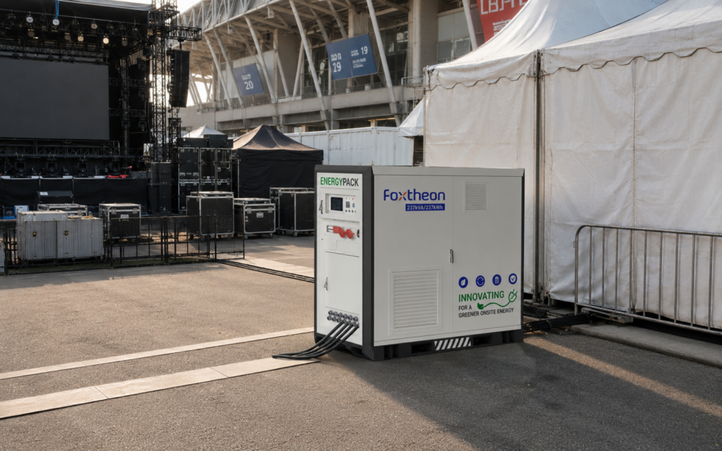
Procurement Standards, Technical Datasheet Evaluation, and Vendor Qualification
When selecting utility-scale or commercial-grade energy storage equipment, engineering, procurement, and construction (EPC) teams must look beyond baseline capacity numbers. A detailed technical evaluation requires assessing multi-variable performance metrics and regulatory compliance standards.
Key Datasheet Parameters to Evaluate
- Round-Trip Efficiency (RTE): The total AC-to-AC power output efficiency, taking into account losses across the inverter, transformer, DC cabling, cell internal resistance, and auxiliary cooling systems. High-tier system architectures aim for an AC RTE of $\ge 86\%\text{ to }88\%$.
- C-Rate Capability & Continuous Run Times: Evaluating whether the operational requirement demands high-power/short-duration output (e.g., 1C for 1 hour duration) or moderate-power/long-duration output (e.g., 0.25C for 4 hours duration).
- Auxiliary Power Consumption: Evaluating standby loss metrics associated with HVAC, liquid pumps, control electronics, and auxiliary power supplies during passive and active states.
- Enclosure Protection and Structural Ratings: Outdoor containerized equipment must feature IP55 or IP66 ingress protection ratings, C4/C5 corrosion protection coatings for coastal/marine environments, and seismic certification (e.g., IEEE 693 compliance).
Compliance, Safety, and Quality Certifications
A compliant li ion battery storage system must strictly conform to comprehensive safety protocols established by international safety and testing organizations. Critical standard frameworks include:
- UL 1973: Safety standard for stationary electrical energy storage batteries, evaluating structural and electrical integrity at module and rack levels.
- UL 9540: Standard for Energy Storage Systems and Equipment, focusing on grid interconnection and complete system-level assembly.
- UL 9540A: Test method for evaluating thermal runaway fire propagation in battery energy storage systems, certifying that thermal runaway events cannot propagate from cell to cell or module to module.
- IEC 62619: International safety requirements for secondary lithium cells and batteries used in industrial applications.
- UN 38.3: Transport safety testing standards for lithium batteries, ensuring safety during air, ocean, and ground freight logistics.
Manufacturers like Foxtheon design containerized solutions engineered against these international safety benchmarks, ensuring structural integrity, simplified site commissioning, and minimal field integration friction for international system integrators and asset operators.
Frequently Asked Questions
Q1: What is the expected service life of a commercial LFP battery storage system?
A1: A commercial-grade LFP battery system operating within specified temperature limits ($20^\circ\text{C} – 25^\circ\text{C}$) typically achieves 6,000 to 8,000 cycles at 80% Depth of Discharge. Under standard daily single-cycle operation, this translates to an operational service life of 15 to 20 years before reaching end-of-life capacity thresholds.
Q2: How does a liquid-cooled storage system compare to an air-cooled system in continuous industrial operation?
A2: Liquid-cooled systems maintain higher internal cell thermal uniformity ($\Delta T \le 3^\circ\text{C}$) and exhibit significantly higher heat transfer coefficients than air-cooled units. This allows for higher continuous charging and discharging rates (C-rates) while reducing auxiliary HVAC parasitic energy consumption by up to 30% to 40%.
Q3: Can an industrial battery storage system integrate with existing continuous thermal generators?
A3: Yes. Modern power systems regularly hybridize energy storage installations with existing diesel or gas generators. The battery storage system handles high-frequency load steps, peak demand spikes, and spinning reserves, allowing the thermal generators to run consistently at optimal, high-efficiency engine load profiles without frequent thermal cycles.
Q4: What compliance standards are essential for validating safety against thermal propagation?
A4: The primary industry testing standard for evaluating thermal runaway propagation is UL 9540A. This test assesses whether a intentionally induced thermal event within a single cell will propagate to adjacent cells or modules within the enclosure. Systems passing this standard demonstrate robust physical and thermal separation controls.
Q5: What electrical protocols are standard for integrating a battery system with a plant-level Energy Management System (EMS)?
A5: System controllers typically communicate using industrial Ethernet and fieldbus protocols, including Modbus TCP/IP, Modbus RTU, CAN bus (CANopen), DNP3, and IEC 61850. These protocols allow high-speed transmission of voltage, temperature, current, SOC, and state-of-health data to centralized supervisory control networks.
Direct Technical Inquiry
Engineering teams, system integrators, and project developers seeking detailed technical specifications, CAD drawings, or system sizing support for industrial energy storage projects can submit technical inquiries directly to our engineering team:
Engineering Consultation & Inquiry Request: Foxtheon Engineering Portal