
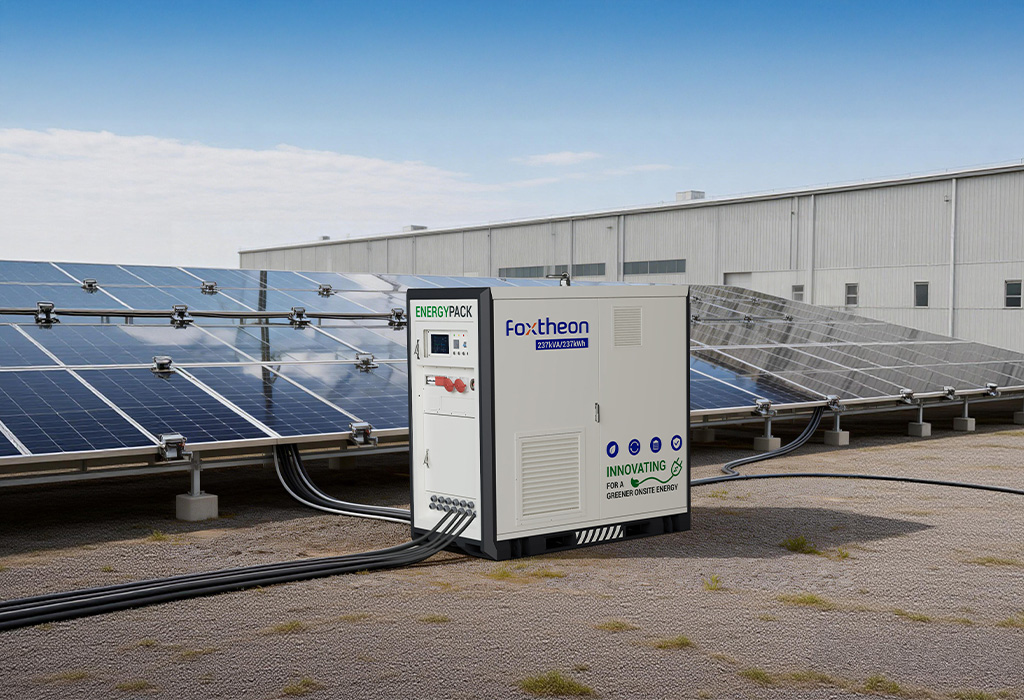
Modern industrial energy systems demand robust, scalable, and highly reliable infrastructure to manage power quality, peak demands, and the integration of intermittent renewable resources. Among the various deployment methodologies, containerised battery storage has emerged as a primary architecture for utility-scale and commercial-and-industrial (C&I) projects. This modular approach leverages standard shipping container dimensions to house battery cells, power conversion systems, thermal management units, and fire suppression systems in a single transportable enclosure.
For engineering, procurement, and construction (EPC) contractors, utility operators, and industrial facility managers, selecting the appropriate system involves evaluating highly technical parameters. Understanding the structural, chemical, and electrical components of these systems is necessary to ensure long-term operational viability and grid compliance. Leading manufacturers such as Foxtheon provide engineered platforms designed to meet these complex operational requirements, bridging the gap between raw battery chemistry and grid-level performance.
Enclosure Engineering, Corrosion Resistance, and Structural Materials
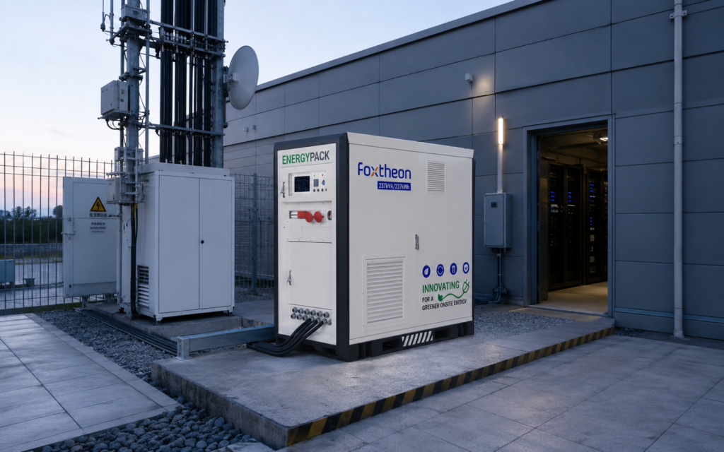
The outer shell of a containerised battery storage unit must protect sensitive electrochemical and power electronics assets from harsh environmental factors. These systems are frequently deployed in environments ranging from high-salinity coastal areas to high-temperature desert regions and sub-zero mountain climates. Consequently, the mechanical and material specifications of the container are paramount.
1. Structural Frame and Panel Composition
Industrial storage enclosures typically utilize standard ISO containers (10ft, 20ft, or 40ft configurations) modified to support heavy internal loads. The structural frame is constructed from high-tensile structural steel, such as Corten steel (GPA or equivalent) or S355 grade steel, providing resistance to atmospheric corrosion and mechanical stress during transit and installation. The wall and ceiling panels are constructed using double-walled sandwich panels containing high-density mineral wool or polyurethane cores. This design achieves specific thermal resistance (R-values) to minimize the energy consumed by the internal HVAC systems while maintaining fire-rated integrity (typically Class A or 120-minute fire ratings conforming to local building codes).
2. Anti-Corrosion Coatings and Environmental Protection
To prevent premature structural degradation, enclosures undergo multi-layer coating processes evaluated under ISO 12944 standards. For inland industrial environments, a C3 or C4 corrosiveness category rating is standard, consisting of an epoxy primer, an epoxy intermediate build coat, and a polyurethane topcoat. For offshore installations or coastal microgrids, a C5-M (Marine) or C5-I (Industrial) high-durability coating system is mandatory. This ensures the container resists salt spray, chemical pollutants, and high humidity over a 20-to-25-year design life.
3. Ingress Protection (IP) Ratings and Airflow Design
The internal environment of the container is strictly segregated. The electrical compartment housing the Power Conversion System (PCS) and switchgear typically requires high ingress protection, often rated at IP54 or IP55, to prevent dust and water entry. In contrast, battery compartments require highly managed air pathways. Motorized louvers with dust filters (conforming to G4 or F7 filtration standards) are employed to regulate airflow during normal operation, closing automatically in the event of fire suppression system activation to seal the chamber.
Thermal Management Systems and Electrochemical Optimization
The performance, safety, and longevity of the battery cells housed within a containerised battery storage enclosure depend heavily on the thermal management architecture. Electrochemical cells, particularly Lithium Iron Phosphate (LFP) and Nickel Manganese Cobalt (NMC), operate optimally within a narrow temperature band, typically between 15°C and 30°C. Deviations from this window accelerate cell degradation and increase the risk of thermal runaway.
Liquid Cooling vs. Forced Air Cooling
Historically, forced air cooling was the standard for containerized systems, relying on high-capacity industrial HVAC systems to circulate conditioned air through battery racks. While cost-effective for low-C-rate applications (under 0.5C), air cooling suffers from thermal non-uniformity, often resulting in temperature differentials of >5°C between cells in the center of a rack and those near the air inlet.
Modern high-density systems increasingly utilize liquid cooling architectures. This setup circulates a coolant mixture (typically water-ethylene glycol) through cold plates integrated directly into the battery modules. Liquid cooling provides several key engineering advantages:
- Thermal Uniformity: Keeps cell-to-cell temperature variations under ±2°C, ensuring uniform degradation rates across the entire battery string.
- Higher Energy Density: Eliminates the wide air plenums required for air circulation, allowing cells to be packed more tightly within the container.
- Efficiency: Liquid has a significantly higher heat capacity than air, reducing the parasitic power consumption of the cooling pumps compared to high-power HVAC fans.
Electrochemical Selection and Degradation Mitigation
For stationary storage, Lithium Iron Phosphate (LFP) has become the dominant chemistry due to its superior thermal stability (thermal runaway threshold at ~270°C compared to ~210°C for NMC) and high cycle life (typically 6,000 to 8,000 cycles at 80% Depth of Discharge). Engineers must calculate the expected capacity fade over the project lifecycle, accounting for both cyclic aging (determined by charge/discharge rates, DoD, and temperature) and calendar aging (passage of time under specific states of charge). Managing these variables requires an intelligent integration of thermal controls and cell-balancing algorithms within the battery management system.
Electrical Architecture: BMS, EMS, and PCS Integration
A functional grid-scale storage system requires seamless communication and energy transfer between three distinct layers: the Battery Management System (BMS), the Power Conversion System (PCS), and the overarching Energy Management System (EMS).
By utilizing engineered platforms from suppliers such as Foxtheon, integrators can access pre-configured systems where these complex interfaces are factory-tested and optimized for immediate grid deployment, reducing commissioning times and integration risks.
| System Layer | Primary Function | Key Parameters Monitored / Controlled | Communication Protocols |
|---|---|---|---|
| Battery Management System (BMS) | Cell-level and rack-level safety, monitoring, and state estimation. | Cell voltage, temperature, State of Charge (SoC), State of Health (SoH), insulation resistance. | CAN bus, Modbus RTU |
| Power Conversion System (PCS) | Bi-directional AC/DC conversion, active and reactive power control. | Grid frequency, AC voltage, phase angle, DC bus voltage, harmonic distortion. | Modbus TCP/IP, IEC 61850 |
| Energy Management System (EMS) | System-level orchestration, load profiling, and microgrid coordination. | Import/export limits, market pricing signals, meteorological data, auxiliary power loads. | DNP3, Modbus TCP/IP, Web APIs |
The BMS operates hierarchically. Slave BMS units monitor individual cell voltages and temperature sensors directly. These report to a Master BMS controlling a complete battery string or rack. The Master BMS manages contactor control, over-current protection, and active/passive balancing. At the system level, the System BMS aggregates data from all racks and coordinates safety shut-offs, communicates with the PCS to limit charge/discharge currents based on thermal limits, and interfaces with the fire suppression system.
The PCS must support grid-forming capabilities in isolated microgrid scenarios and grid-following capabilities when connected to a stable utility grid. Key functionalities include black start capability (the ability to energize a local grid from a completely de-energized state) and rapid response times (often under 50 milliseconds) for frequency containment and transient voltage support.
Grid-Scale and Commercial Application Vectors
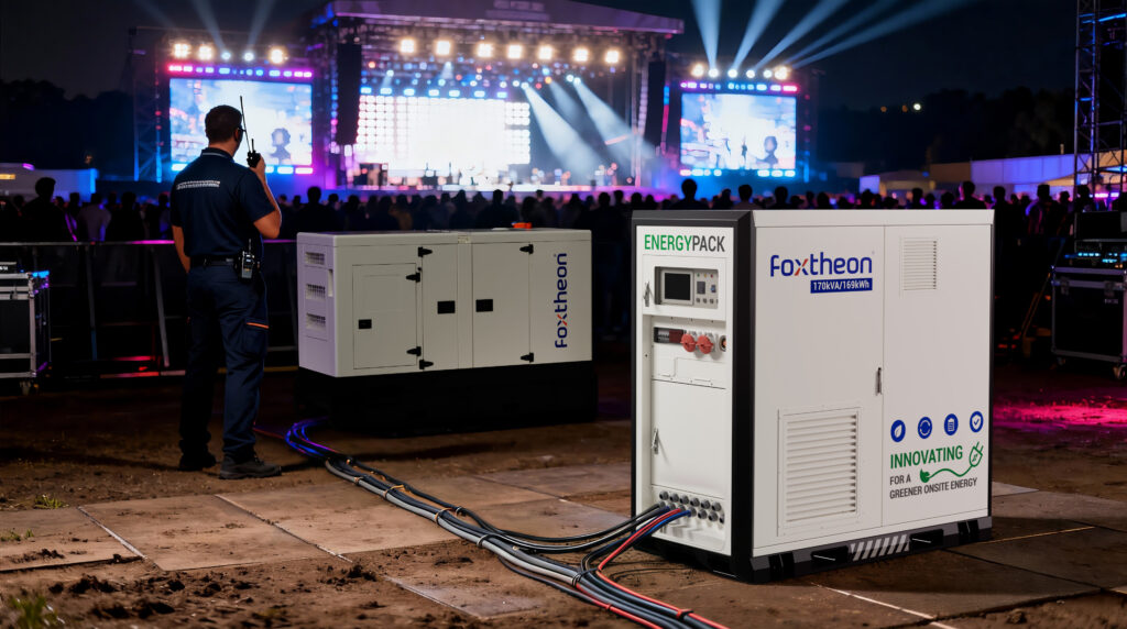
The versatility of containerised battery storage makes it suitable for a wide range of C&I and utility applications. Rather than substituting existing power generation assets, these systems are integrated alongside them to enhance efficiency, stabilize local networks, and improve power quality.
- Peak Shaving and Demand Charge Management: Industrial facilities often face high peak demand charges from utilities. By discharging the containerized storage system during periods of peak factory consumption, facilities reduce their maximum draw from the grid, lowering their energy tariffs.
- Renewable Energy Smoothing: Co-locating storage with solar photovoltaic (PV) or wind installations mitigates the fast power fluctuations caused by cloud cover or shifting wind speeds. The storage system acts as a buffer, absorbing excess energy during peak generation and discharging it during low-generation periods.
- Microgrid Optimization and Synchronization: In remote regions, mining operations, or islanded environments, storage systems operate in tandem with existing diesel or natural gas generators. The battery system manages transient load changes immediately, allowing the generators to run at their most efficient load points, thereby reducing maintenance intervals and fuel consumption.
- Frequency Regulation and Ancillary Services: On a utility scale, containerized systems participate in frequency response markets. They rapidly inject or absorb power to maintain the grid frequency within strict operational limits (e.g., 50Hz ±0.2Hz in European networks).
Sourcing Best Practices, Certification Standards, and Technical Evaluation
Procuring a high-performance containerised battery storage system requires a rigorous evaluation of supplier capability, safety certifications, and compliance standards. This step is necessary to secure project financing, obtain local building permits, and ensure operational safety.
1. Core Certification Standards
Sourcing teams must verify that the proposed system holds valid certifications from accredited testing laboratories (such as TÜV, UL, or Intertek). Key standards include:
- UL 9540: The standard for safety of energy storage systems and equipment, covering the electrical, electrochemical, mechanical, and environmental safety of the complete system.
- UL 9540A: Testing methodology for evaluating thermal runaway fire propagation in battery energy storage systems. Compliance with UL 9540A is crucial for determining safe installation distances and fire protection designs.
- IEC 62619: Safety requirements for secondary lithium cells and batteries for use in industrial applications.
- NFPA 855: Standard for the Installation of Stationary Energy Storage Systems, detailing spacing, ventilation, and fire suppression system design requirements.
2. Fire Suppression and Safety Systems
Safety within the containerized enclosure is managed via multi-tier mitigation strategies. Early warning gas detection systems (such as carbon monoxide and off-gas detectors) identify cell venting before thermal runaway occurs. If thermal runaway is detected, aerosol-based fire suppression systems (e.g., Stat-X or FirePro) or gaseous agents (such as Novec 1230 or FM-200) deploy to extinguish flame propagation without damaging adjacent electronics. Additionally, deflagration panels (explosion venting) conforming to NFPA 68 must be integrated into the container roof to safely vent overpressures caused by gas accumulation.
3. Testing and Commissioning Protocols
Before shipment, a comprehensive Factory Acceptance Testing (FAT) protocol should be executed at the manufacturer’s facility. FAT includes high-voltage insulation testing, thermal loop testing, full-cycle capacity verification, and simulated fault injections to verify BMS safety limits. Upon arrival on site, Site Acceptance Testing (SAT) is performed to ensure no damage occurred during transit and that integration with local SCADA and utility grid interfaces is functioning as designed.
Frequently Asked Questions
Q1: What is the expected operational lifespan of a containerised battery storage system?
A1: The physical container and auxiliary systems (HVAC, structural frame) are designed for a 20-to-25-year service life. The lifespan of the battery cells themselves is measured in cycles and operational degradation. For high-quality LFP cells managed under optimal thermal conditions, the battery pack typically retains 70% to 80% of its nominal capacity after 6,000 to 8,000 equivalent full cycles, which correlates to roughly 10 to 15 years of daily cycling before battery cell replacement or augmentation is required.
Q2: Can liquid-cooled systems operate reliably in extremely cold environments?
A2: Yes. Liquid-cooled systems utilize a coolant containing an appropriate ratio of ethylene glycol to water, preventing freezing down to temperatures below -30°C. In sub-zero environments, the liquid cooling loop operates in reverse using internal electric heaters integrated into the chiller/heater unit to warm the battery modules to their optimal operating range before charging or discharging cycles begin.
Q3: How do containerised battery storage systems comply with local noise regulations in urban zones?
A3: The primary noise sources in a containerized storage system are the HVAC condenser fans and the PCS cooling fans. Standard containers exhibit noise levels around 65 to 75 dBA at a distance of 1 meter. For noise-sensitive environments, manufacturers can integrate low-noise variable-frequency fans, acoustic duct silencers, and sound-absorbing insulation panels inside the container walls, reducing emissions below 55 dBA.
Q4: What is the differences between AC-coupled and DC-coupled container architectures?
A4: In an AC-coupled architecture, the batteries have their own dedicated bi-directional inverter (PCS) that outputs AC power directly to the main AC busbar, which is highly compatible with existing facilities. In a DC-coupled architecture, the batteries and renewable generation sources (like solar PV) connect directly to a shared DC bus via DC-DC converters, which then feeds into a single, shared central inverter. DC coupling can offer higher round-trip efficiency for solar-plus-storage applications but is more complex to integrate into brownfield sites.
Q5: How does the system handle utility grid outages when operating in grid-following mode?
A5: When a utility grid outage occurs, standard grid-following inverters must shut down immediately to prevent islanding (exporting power to a dead utility line, which poses a hazard to utility workers), in accordance with standards such as IEEE 1547. However, if the system is designed with grid-forming capabilities and external microgrid controllers, it can isolate the local facility using an automatic transfer switch (ATS) and establish a local grid voltage and frequency, maintaining continuous power to local critical loads.
B2B Project Inquiry
Developing high-capacity energy storage installations requires customized engineering calculations, including load profile analyses, reactive power requirements, and localized environmental adaptation. If you are preparing a technical specification or require detailed product datasheets, engineering drawings, or pricing structures for your upcoming commercial or utility-scale projects, please submit your query directly to our engineering division.
Contact Foxtheon directly via our technical procurement portal: https://www.foxtheon.com/