
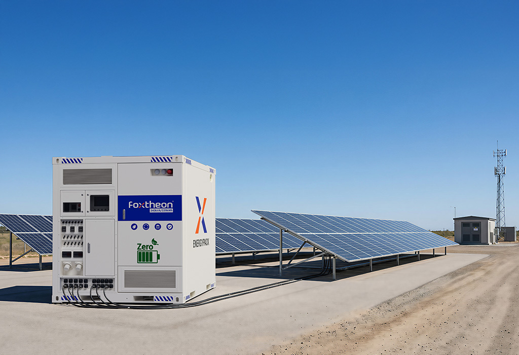
Commercial and industrial (C&I) facilities operate under rigorous energy requirements, where grid reliability, demand charges, and power quality directly impact operational overhead. Modern facilities are transitioning toward proactive energy management strategies to mitigate price volatility and secure continuous operations. A primary asset in this transition is the integration of commercial battery storage technology. These systems allow enterprises to manage peak demand, optimize local generation, and maintain power continuity during utility disturbances.
To implement these systems effectively, facility managers and system integrators must understand the underlying technical specifications, chemical compositions, and engineering standards. Modern hardware engineered by advanced developers like Foxtheon utilizes sophisticated power electronics and cell topologies to deliver reliable, long-term performance under demanding load conditions.
1. Technical Architecture of Commercial Battery Energy Storage Systems (BESS)
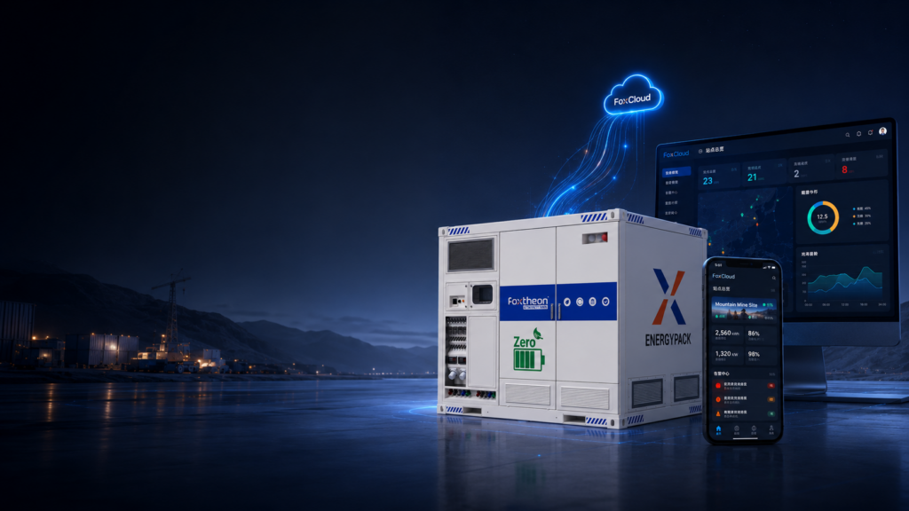
A functional commercial battery storage unit is an integrated ecosystem comprising electrochemical cells, thermal management, power conversion, and control systems. Each subsystem must be precisely matched to ensure operational safety, high round-trip efficiency (RTE), and system longevity.
Electrochemical Cell Chemistry: LFP vs. NMC
Stationary commercial storage systems rely primarily on lithium-ion chemistry, with Lithium Iron Phosphate (LiFePO4 or LFP) and Nickel Manganese Cobalt (NMC) being the primary choices. LFP chemistry has emerged as the industry standard for C&I applications due to its distinct safety and degradation profiles:
- Thermal Stability: LFP cells exhibit a high thermal runaway threshold (approximately 270°C) compared to NMC cells (approximately 210°C). This significantly reduces the risk of self-sustaining exothermic reactions.
- Cycle Life: LFP configurations typically sustain 6,000 to 8,000 charge-discharge cycles at an 80% Depth of Discharge (DoD) before capacity degrades to 80% of its original rating. In contrast, NMC chemistry generally yields 2,000 to 3,000 cycles under similar operational profiles.
- Materials and Sustainability: LFP cells do not utilize cobalt, avoiding ethical sourcing complications and lowering environmental impact during decommissioning.
The mechanical construction of these cells also varies. Prismatic cell designs are highly favored in commercial applications because of their rigid aluminum casings, efficient heat dissipation pathways, and superior volumetric packaging efficiency within industrial racks.
Power Conversion Systems (PCS) and Inverter Topologies
The Power Conversion System (PCS) serves as the bi-directional interface translating direct current (DC) stored in the batteries to alternating current (AC) compatible with the facility’s distribution board and the utility grid. Modern PCS units utilize silicon carbide (SiC) or insulated-gate bipolar transistor (IGBT) switching topologies to achieve conversion efficiencies exceeding 98%.
Key operational capabilities of the PCS include:
- Grid-Following vs. Grid-Forming: Grid-following inverters synchronize with the existing utility voltage and frequency reference. Grid-forming inverters can establish a local voltage and frequency reference, allowing the facility to operate in islanded mode during utility outages.
- Four-Quadrant Operation: This enables the active management of both active power (P) and reactive power (Q), allowing the system to assist in power factor correction and local voltage regulation.
- Response Time: High-performance inverters transition from idle to full rated power output in under 20 milliseconds, which is necessary for transient voltage support and seamless backup power transition.
Multi-Tiered Battery Management Systems (BMS)
Operational safety and longevity are governed by a multi-tiered Battery Management System (BMS). The BMS maintains each cell within its Safe Operating Area (SOA) by continuously monitoring parameters such as cell voltage, pack current, and localized temperatures.
The standard architecture includes:
- Level 1 (Cell/Module Level): Collects raw sensor data and executes passive or active cell balancing to ensure uniform state of charge (SoC) across series-connected cells.
- Level 2 (Rack/String Level): Aggregates module data, calculates overall state of health (SoH), manages contactors, and communicates with the system-level controller.
- Level 3 (System Level): Coordinates multiple battery racks, interfaces with the local Energy Management System (EMS), and executes safety shutdowns via hardwired emergency stop circuits.
2. Operational Use Cases and Integration Strategies
The economic and operational value of implementing a commercial battery storage system is realized through target applications integrated into the site’s energy management strategy.
Peak Shaving and Demand Charge Mitigation
Utility companies charge commercial customers not only for total energy consumed (kWh) but also for the maximum rate of consumption (kW) within a billing cycle, known as demand charges. These charges can represent a substantial portion of the total monthly utility bill.
Peak shaving involves configuring the EMS to monitor real-time facility power consumption at the main service entrance. When the load approaches a predefined threshold, the EMS commands the battery system to discharge, supplying a portion of the load locally. This caps the metered utility demand, lowering monthly demand fees without requiring operational shutdowns or curtailing production processes.
Load Shifting and Time-of-Use (ToU) Optimization
Many utilities utilize Time-of-Use pricing structures, where electricity costs vary based on the time of day and season. By utilizing energy storage, facilities can execute load shifting strategies:
- Charging Phase: The battery charges during off-peak periods when electricity tariffs are at their lowest, or directly from on-site renewable generation such as solar PV.
- Discharging Phase: The battery discharges to power facility loads during peak periods when utility tariffs are highest, avoiding expensive energy purchases from the grid.
Hybrid Integration with Co-located Generation Assets
Rather than replacing existing infrastructure, modern battery systems are designed to operate alongside existing assets, such as diesel or natural gas generators. In a hybrid microgrid configuration, the battery serves as a dynamic buffer. When a high-power transient load starts up (e.g., a large industrial motor), the battery provides immediate power, preventing voltage dips and allowing the backup generator to ramp up slowly and run at its most efficient thermal load. This reduces fuel consumption, minimizes engine wear, and reduces wet stacking in diesel units.
3. Mitigating Operational and Engineering Challenges
Deploying energy storage assets in commercial settings requires addressing specific thermal, safety, and integration requirements to ensure safe operations over the system’s design life.
Thermal Management Systems
Battery degradation is highly temperature-dependent; sustained operation above 40°C accelerates capacity loss, while operation below 0°C limits charge acceptance. Two main thermal management methods are utilized in commercial designs:
- Forced Air Cooling: Utilizes fans and internal ducting to pass conditioned air through the battery modules. While simpler in design, air cooling can result in internal temperature gradients across large battery racks, leading to uneven cell aging.
- Liquid Cooling: Uses closed-loop cooling plates circulating a glycol-water mixture in direct contact with the cell casings. Liquid cooling offers significantly higher heat transfer coefficients, keeping the cell-to-cell temperature differential within 3°C. This thermal uniformity extends cycle life and allows for safe operation under high C-rate charging and discharging.
Safety Standards and Fire Suppression (NFPA 855)
Safety is a primary design factor for indoor and outdoor commercial installations. System designs must comply with international standards to mitigate and contain thermal runaway events:
- UL 1973: Tests the safety of battery cells, modules, and racks under electrical, mechanical, and thermal abuse conditions.
- UL 9540 and UL 9540A: Standard for safety of energy storage systems and equipment, including rigorous testing of thermal runaway fire propagation behavior.
- NFPA 855: Standard for the Installation of Stationary Energy Storage Systems, specifying structural separation distances, ventilation requirements, and fire suppression systems.
Modern outdoor containerized systems integrate automated aerosol or clean-agent fire suppression systems (such as Novec 1230), coupled with combustible gas detection (to detect off-gassing before thermal runaway occurs) and deflagration venting panels.
4. Sourcing and Selection Criteria for Industrial Buyers
Procuring a commercial battery storage system involves evaluating engineering specifications beyond simple capacity metrics. Project developers and procurement officers must prioritize reliability, scalability, and integration support.
Modular Architecture and Scalability
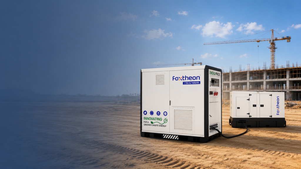
Commercial energy profiles are rarely static. A modular design allows facilities to scale energy storage capacity in step with operational growth. Scalable systems, such as those designed by Foxtheon, utilize standardized rack configurations that can be expanded in parallel. This design minimizes upfront capital commitment while ensuring that future power and energy capacity requirements can be integrated without requiring a complete overhaul of the existing electrical distribution board or PCS.
Key Selection Metrics
When comparing system integrators and equipment manufacturers, technical teams should evaluate the following parameters:
- Round-Trip Efficiency (RTE): The ratio of energy retrieved from the battery to the energy put in, measured at the AC connection point. High-quality systems should demonstrate an AC-to-AC RTE of 85% to 90%.
- Auxiliary Power Consumption: The energy consumed by the system’s thermal management, BMS, and controller units. High auxiliary consumption reduces the net efficiency of the installation.
- Guaranteed Capacity Retention: A performance warranty specifying the remaining usable capacity of the battery over a set period (typically 10 years) or a cumulative energy throughput limit (expressed in MWh).
5. Frequently Asked Questions
Q1: How does commercial battery storage improve local power quality?
A1: The system’s bi-directional inverter continuously monitors grid voltage and frequency. It can inject or absorb active and reactive power within milliseconds to compensate for voltage sags, swells, and transient harmonics, ensuring a stable power supply to sensitive electronic equipment and machinery within the facility.
Q2: What is the differences between LFP and NMC battery chemistries in C&I projects?
A2: Lithium Iron Phosphate (LFP) is generally preferred for stationary commercial storage because of its superior thermal stability, lower fire risk, and longer cycle life (often double that of NMC). Nickel Manganese Cobalt (NMC) has higher volumetric energy density, which is advantageous for space-constrained mobile applications but less significant for typical ground-mounted or containerized commercial installations.
Q3: Can a commercial battery system work alongside existing diesel generators?
A3: Yes, modern energy storage systems integrate with existing diesel generators via hybrid microgrid controllers. The battery absorbs transient load spikes instantly, allowing the generator to operate at a steady, efficient load profile. This hybrid operation reduces fuel consumption and limits generator wear and tear.
Q4: What parameters determine the optimal sizing of a commercial energy storage system?
A4: Sizing is determined by analyzing 15-minute interval utility billing data to identify peak demand periods, load duration curves, and base-load characteristics. The target applications (e.g., peak shaving vs. long-duration backup) dictate the required power (kW) to energy (kWh) ratio of the battery system.
Q5: How does liquid cooling compare to air cooling in BESS?
A5: Liquid cooling provides superior thermal uniformity, maintaining cell-to-cell temperature variations under 3°C. This precise temperature control prevents uneven cell aging, lowers auxiliary power consumption in hot climates, and supports higher charge/discharge rates without risking thermal runaway, compared to traditional forced-air cooling systems.
Technical Sourcing & Inquiry
For detailed technical specifications, system sizing calculations, or to discuss integrating a modular energy storage solution with your existing commercial infrastructure, submit your electrical profile and project requirements directly to our engineering department.
To request a technical consultation or a customized system quote, please contact the engineering and product team at Foxtheon through our online portal: Foxtheon Commercial Inquiry Support.