
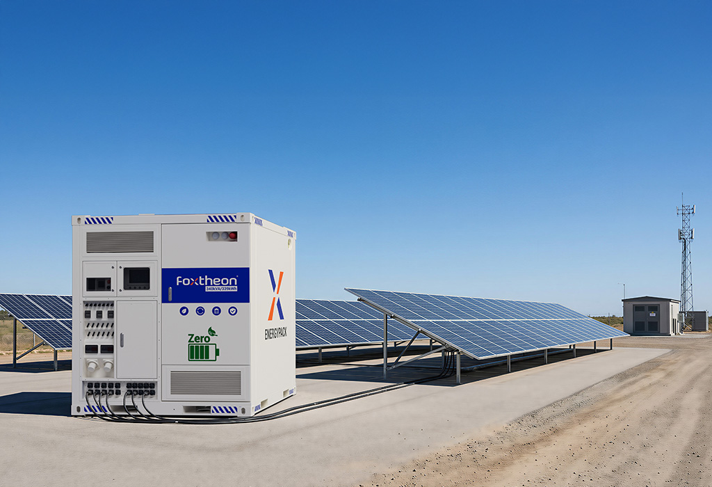
Modern electrical distribution networks undergo continuous transformation as variable renewable generation mixes with conventional transmission infrastructure. Traditional central-station power plants relied on high operational inertia from heavy spinning mass to maintain system frequency. The reduction of synchronized inertia requires dynamic, sub-second buffer mechanisms to guarantee network equilibrium. Utility-scale grid battery storage systems serve as fundamental balancing assets, providing instant active power compensation, voltage regulation, and ramping capabilities necessary to maintain grid stability.
The transition toward decentralized distribution demands an examination of dynamic system control, power conversion topologies, thermal safety protocols, and long-term asset balance. Deploying utility-scale energy storage requires alignment between chemical storage cells, bidirectional power electronics, software intelligence, and regional grid code compliance.
Technical Architecture of Utility-Scale Storage Systems
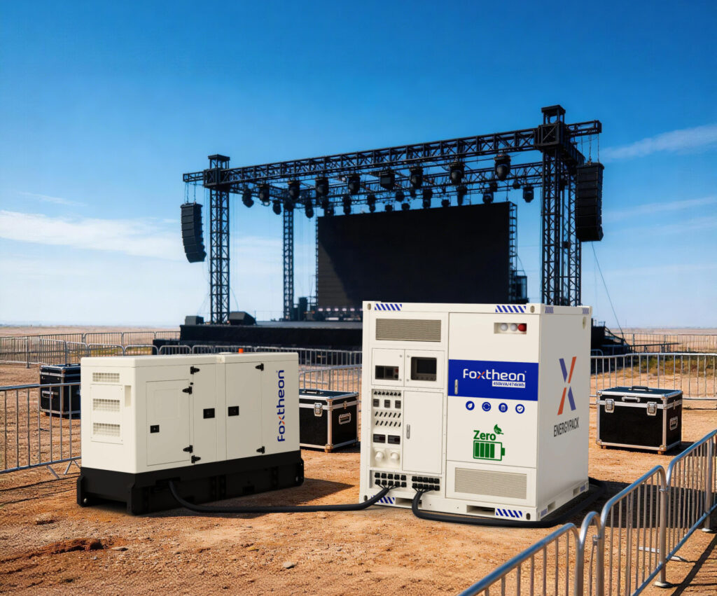
A comprehensive utility-scale energy storage installation consists of multiple interdependent engineering layers. The base layer comprises electrochemical cells organized into modules, racks, and enclosures. This direct current (DC) block connects to a high-efficiency Power Conversion System (PCS) that converts direct current to alternating current (AC) for high-voltage transformation and transmission interconnection.
Electrochemical Cell Chemistries and Degradation Mechanics
Selection of battery chemistry defines the operational envelope, cycle life, thermal boundaries, and discharge profiles of the installation. Lithium Iron Phosphate (LiFePO4 or LFP) has established itself as the dominant chemistry for stationary energy storage due to its structural stability and extended cycle life under heavy duty cycles.
- Lithium Iron Phosphate (LFP): Offers high thermal runaway thresholds (~270°C) and superior calendar aging traits. LFP cells withstand between 6,000 to 10,000 full depth-of-discharge (DoD) cycles at 0.5C rate before reaching 80% capacity retention. The Olivine crystal structure resists mechanical stress during continuous lithium ion intercalation.
- Nickel Manganese Cobalt (NMC): Provides higher volumetric energy density, making it suitable where spatial footprints are strictly limited. However, lower thermal decomposition thresholds (~210°C) necessitate complex, redundant thermal mitigation and fire suppression controls.
Cell degradation follows two primary mechanisms: calendar aging and cycle aging. Calendar aging stems from Solid Electrolyte Interphase (SEI) layer growth at the anode surface, accelerated by elevated state of charge (SoC) and high ambient temperatures. Cycle aging results from mechanical strain during ion movement, structural particle cracking, and active material dissolution. System design must incorporate active cooling strategies to keep operational cell temperatures between 15°C and 25°C, limiting degradation rates over a 15-to-20-year operational life.
Power Conversion System (PCS) and Inverter Topologies
The Power Conversion System serves as the bridge between the DC battery bank and the AC transmission network. Modern grid-tied inverters utilize high-frequency Insulated-Gate Bipolar Transistors (IGBT) or Silicon Carbide (SiC) MOSFET semiconductors to achieve conversion efficiencies above 98.5%.
Inverters operate under two distinct structural controls:
- Grid-Following (GFL) Inverters: Rely on a Phase-Locked Loop (PLL) to detect grid voltage angle and frequency, synchronizing output current to the external network. GFL systems function effectively in strong grid conditions where a stable voltage reference exists.
- Grid-Forming (GFM) Inverters: Function as voltage sources behind virtual impedance, establishing localized voltage and frequency references. GFM algorithms enable black-start capability, synthetic inertia emulation, and stable operation under low short-circuit ratio (SCR) conditions.
Modern utility installations incorporate bidirectional topology capable of sub-10-millisecond response times for dynamic switching between charge and discharge modes. Total Harmonic Distortion (THD) must be controlled below 3% to prevent high-frequency noise injection into medium-voltage distribution lines.
Thermal Management and Liquid Cooling Infrastructure
Thermal regulation directly impacts system safety, round-trip efficiency (RTE), and economic longevity. While legacy installations utilized forced air cooling, contemporary utility-scale grid battery storage configurations utilize direct-to-plate liquid cooling circuits.
Liquid cooling networks circulate a water-glycol coolant directly through cold plates integrated into the cell modules. This architecture yields several technical advantages over traditional air cooling:
- Heat transfer coefficient up to 25 times higher than air, maintaining cell-to-cell thermal variance under 2°C across large multi-megawatt blocks.
- Parasitic energy consumption reduction up to 30%, increasing net usable energy output across full daily charge-discharge cycles.
- Inherent containment barriers that limit thermal runaway propagation between adjacent cell groups.
Ancillary Services and Grid Stabilization Mechanisms
Utility-scale energy storage assets deliver fast-acting ancillary services required by transmission system operators (TSOs) and distribution system operators (DSOs). The high ramp rates of electrochemical storage make these assets ideal for real-time network correction.
Fast Frequency Response (FFR) and Synthetic Inertia
System frequency deviates when active power generation does not match dynamic consumer load. Traditional thermal turbines provided kinetic energy (inertia) to slow frequency decay during sudden trip events. As non-synchronous renewable generation replaces heavy turbines, system inertia declines, resulting in steep rate-of-change-of-frequency (RoCoF) conditions.
Advanced grid battery storage deployments utilize Fast Frequency Response protocols. Upon detecting a frequency deviation past a deadband threshold (e.g., ±0.05 Hz), the battery management and inverter control loops trigger maximum active power injection within 100 to 200 milliseconds. Synthetic inertia algorithms simulate mechanical governor responses, altering active power output in direct proportion to calculated RoCoF values.
Voltage Regulation and Reactive Power Compensation (VAR)
Local grid voltage fluctuates due to inductive load variations, variable localized generation, and feeder impedance shifts. Modern multi-megawatt storage systems supply or absorb reactive power (VAR) independently of active power (P) states within the full four-quadrant operating envelope of the inverter.
By injecting reactive power during undervoltage events or absorbing reactive power during light-load overvoltage conditions, storage systems maintain line voltage profiles within statutory limits (typically ±5% of nominal voltage) without stressing mechanical tap changers on distribution transformers.
Peak Shaving and Energy Time-Shifting Dynamics
Energy time-shifting involves storing low-cost off-peak power during periods of overgeneration and dispatching energy during high-demand windows. Peak shaving flattens feeder loading profiles, preventing thermal overload on underground cables, substations, and overhead lines during maximum peak hours.
By absorbing local distribution surges, storage deployments reduce line congestion and defer expensive distribution line upgrades. System control logic manages dynamic State of Charge targets to balance peak shaving readiness with sudden frequency response availability.
Hardware Integration and Structural Engineering Standards
Designing utility installations requires multi-layered engineering to meet structural integrity, electrical insulation, electromagnetic compatibility (EMC), and severe fire protection standards.
Enclosure Design and Environmental Isolation
Outdoor utility systems are subject to ambient temperature variations, humidity, dust intrusion, corrosive marine atmospheres, and seismic activity. Containerized systems utilize IP65 or NEMA 4X rated double-walled steel enclosures with integrated C5-M anti-corrosion coatings.
Structural validation requires compliance with seismic criteria such as IEEE 693, ensuring that internal rack frames, busbar supports, and internal liquid piping withstand physical acceleration forces during seismic events without loss of electrical isolation or structural yield.
Safety Systems and Thermal Runaway Containment
Preventing cascading thermal runaway is a primary design objective for industrial energy storage. Thermal runaway occurs when internal short-circuits, mechanical damage, overcharging, or external heat input trigger exothermic chemical reactions within the battery cell, releasing flammable gases (hydrogen, carbon monoxide, methane).
Modern safety design integrates several active and passive safety layers:
- Off-gas Detection: Early-stage monitoring sensors detect trace amounts of volatile organic compounds (VOCs) and hydrogen gas before thermal runaway occurs, triggering automated cell isolation and emergency shutdown protocols.
- Deflagration Venting: Explosion protection panels designed in accordance with NFPA 68 safely direct internal pressure waves upward and away from surrounding hardware and operating personnel.
- Fire Suppression Agents: Dual-stage suppression combines clean agents (Novec 1230 or FM-200) for initial gas suppression with high-volume water deluge interfaces conforming to NFPA 855 standards for localized thermal cooling.
Integration of specialized enclosure platforms engineered by vendors such as Foxtheon incorporates integrated structural barriers, dedicated thermal isolation, and automated fire mitigation systems to ensure high operational safety standards across diverse utility sites.
Software Architecture and Control Logic Protocols
An industrial storage asset relies on hierarchical software stacks to manage microsecond cell switching up to macro-level grid dispatch orchestration.
Hierarchical System Control Logic
The system control architecture spans three distinct functional tiers:
- Tier 1 – Battery Management System (BMS): Operates directly at cell, module, and rack levels. The BMS monitors cell voltages, temperatures, balancing currents, and insulation resistance. It calculates State of Charge (SoC) and State of Health (SoH), ensuring individual cells remain within safe operating limits.
- Tier 2 – Power Plant Controller (PPC): Operates at the facility level, coordinating multiple inverter blocks, medium-voltage transformers, switchgear, and auxiliary environmental systems. The PPC executes local active/reactive power control, voltage regulation routines, and power factor correction.
- Tier 3 – Energy Management System (EMS): Communicates with central grid operators via standard utility protocols. The EMS processes forecast data, electricity pricing, grid commands, and health metrics to optimize overall dispatch strategy.
Communication Protocols and Cybersecurity Interconnection
Utility-grade assets require low-latency, deterministic control communication networks. Standard fieldbus protocols include:
- IEC 61850: The global standard for power utility automation, enabling object-oriented data structures for rapid substation communication over GOOSE (Generic Object Oriented Substation Events) messaging systems.
- DNP3 / Modbus TCP: Widely utilized across legacy grid network architectures to transmit telemetry data, system state metrics, and remote control commands from Supervisory Control and Data Acquisition (SCADA) systems.
Cybersecurity controls must meet NERC CIP (North American Electric Reliability Corporation Critical Infrastructure Protection) directives. Firewalls, encrypted VPN channels, transport layer security (TLS 1.3), and strict role-based access control (RBAC) are applied to protect edge devices from non-authorized remote commands.
Procurement and System Engineering Criteria
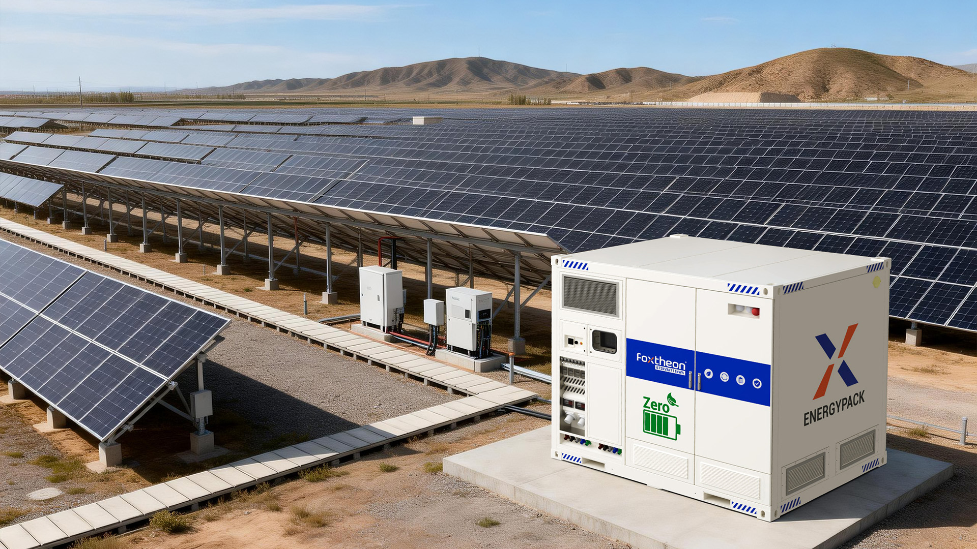
Selecting full-scale equipment for grid battery storage projects requires rigorous technical validation beyond nominal system power and capacity parameters. Technical procurement documentation must evaluate operational degradation curves, cycle life limits, and physical serviceability constraints.
Technical Evaluation Criteria for Engineering Decision Makers
Engineers, system integrators, and project planners should evaluate prospective storage technologies against standardized performance indicators:
- Round-Trip Efficiency (RTE): Total AC-to-AC energy efficiency, factoring in losses from inverters, step-up transformers, internal cell resistance, and auxiliary cooling loads. High-grade systems target an AC RTE exceeding 86% across full system life.
- C-Rate Capability: The measure of charge or discharge speed relative to total system capacity. Systems designed for frequency response require high C-rate bursts (1C to 2C), whereas long-duration energy shifting models operate optimized profiles at lower rates (0.25C to 0.5C).
- Thermal Runaway Testing (UL 9540A): Fire safety testing reports at the cell, module, unit, and installation level must be evaluated to confirm that cell failure will not propagate beyond single localized clusters.
- Auxiliary Parasitic Loads: System auxiliary power draw (HVAC, pumps, controllers) directly impacts total output. Designs optimized by providers like Foxtheon reduce parasitic consumption through intelligent thermal loop controls.
Deploying specialized modular platforms reduces field assembly labor, simplifies medium-voltage interconnects, and establishes consistent, factory-tested safety controls across utility grid nodes.
Technical Frequently Asked Questions
Q1: What is the main structural difference between grid-following and grid-forming inverters in battery storage?
A1: Grid-following (GFL) inverters rely on an established external utility voltage and frequency reference provided by the transmission network to align their current injection via Phase-Locked Loops. Grid-forming (GFM) inverters act as independent voltage sources, utilizing specialized control algorithms to set local frequency and voltage references. GFM systems provide virtual inertia, support low short-circuit ratio (SCR) networks, and enable black-start functionality during total grid blackout conditions.
Q2: How do liquid cooling systems improve long-term battery performance compared to forced-air systems?
A2: Liquid cooling systems provide superior thermal conductivity, maintaining cell temperatures within a tight operational range (typically under 2°C variation across modules). This thermal uniformity prevents localized hot spots, minimizes internal cell impedance imbalance, reduces calendar and cyclic degradation, and decreases auxiliary parasitic energy draw compared to air cooling fans, resulting in higher net system efficiency.
Q3: Why is LFP chemistry preferred over NMC for long-duration utility-scale applications?
A3: Lithium Iron Phosphate (LFP) delivers greater structural chemical stability, higher thermal runaway thresholds (~270°C compared to ~210°C for NMC), and extended cycle life (6,000–10,000 cycles at 80% Depth of Discharge). LFP does not use cobalt, reducing raw material supply vulnerabilities while offering superior safety margins under continuous cycling profiles characteristic of utility operations.
Q4: How do utility-scale grid battery storage installations respond to rapid frequency deviations?
A4: Upon detecting a frequency anomaly exceeding predetermined deadband limits, high-speed telemetry and power controllers signal the Power Conversion System (PCS). Utilizing fast power conversion electronics, the system transitions from standby or charge mode to full discharge output within 100 milliseconds, injecting active power to halt frequency degradation and stabilize the grid.
Q5: What certifications are mandatory for installing commercial and utility-scale energy storage enclosures?
A5: Core standard compliance includes UL 1973 (for battery modules), UL 1741 SB / IEEE 1547-2018 (for grid-interconnected inverters), UL 9540 (for complete integrated energy storage systems), and UL 9540A (thermal runaway propagation fire testing). Facilities must also align with local structural code standards, NFPA 855 installation guidelines, and NFPA 68/69 explosion protection specifications.
Engineering Consultation and Technical Inquiries
Integrating large-scale energy storage assets into existing distribution systems requires careful component sizing, thermal strategy selection, grid code compliance verification, and software setup. Foxtheon provides utility-scale and commercial energy solutions designed for complex operating requirements.
To consult with an application engineer regarding system configuration options, single-line diagrams, technical datasheets, or grid interconnection compliance parameters, submit your detailed project scope directly through our technical engineering portal:
Engineering Inquiry Desk: https://www.foxtheon.com/