
Industrial electrification and heavy commercial operations require uninterrupted, high-quality power delivery. Facilities operating in isolated locations, grid-edge regions, or demanding industrial manufacturing zones traditionally depend on reciprocating combustion engines to manage base and peak loads. Integrating high-yield photovoltaic arrays and high-capacity battery storage alongside existing thermal generation forms the basis of modern distributed power. Correctly specified hybrid energy systems optimize fuel consumption, mitigate mechanical wear on engine assets, and stabilize medium-voltage industrial distribution networks.
Achieving stable operation across multi-source topologies requires rigorous engineering, from the selection of semi-conductor materials and cell chemistries to the microsecond synchronization of power electronics. Rather than seeking to substitute existing generating infrastructure, progressive system architects engineer architectures where thermal gensets, solar arrays, and electrochemical storage operate synergistically. Advanced system integrators such as Foxtheon deliver intelligent control platforms that orchestrate these multi-generation assets into cohesive, resilient power plants capable of handling heavy inductive loads and dynamic step changes.
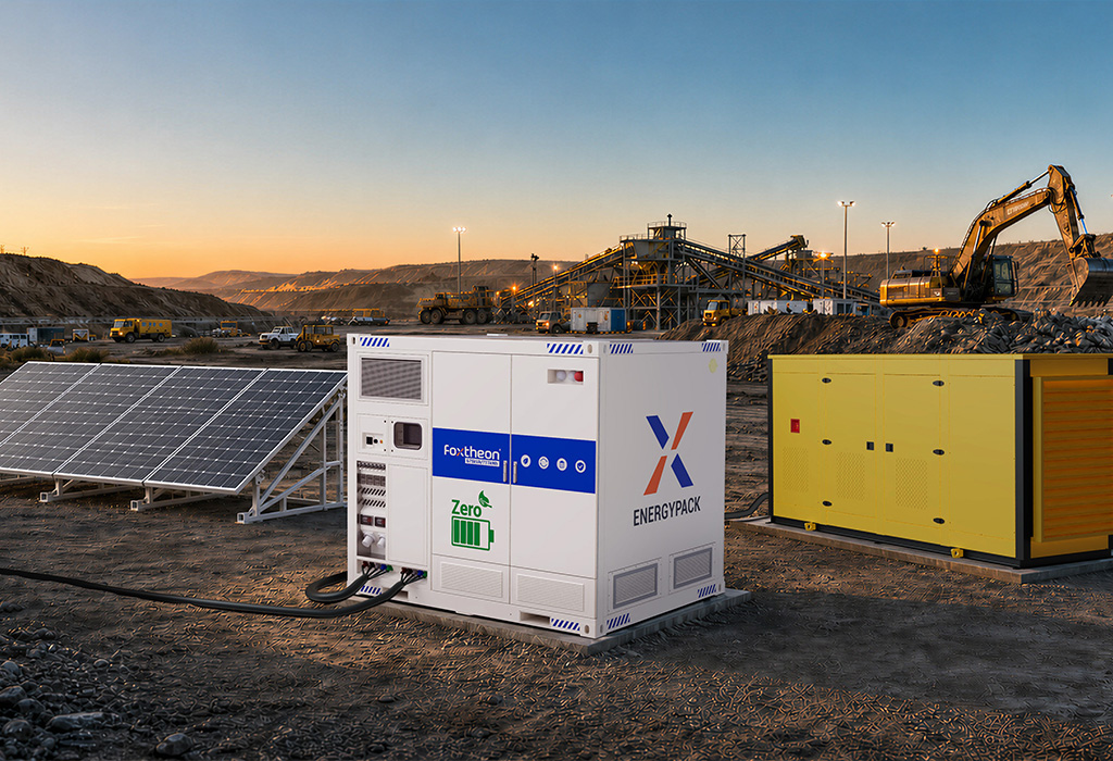
Topological Selection: AC-Coupled vs. DC-Coupled Microgrid Architectures
The choice between AC-coupled and DC-coupled architectures forms the primary decision gate when designing industrial microgrids. Each topology imposes distinct electrical characteristics, inverter efficiencies, and switchgear configurations.
AC-Coupled Topologies for Brownfield Industrial Projects
AC coupling connects all energy generation and storage assets directly to a common alternating current distribution bus, typically operating at 400V, 480V, or medium voltages such as 11kV or 33kV via dedicated step-up transformers. In this topology:
- The existing generator sets feed the primary AC switchboard directly through circuit breakers synchronized via automatic synchronizers.
- The photovoltaic generation field utilizes string or central inverters to convert DC solar yields into three-phase AC synchronized with the local network frequency.
- The Battery Energy Storage System (BESS) interfaces through a bidirectional Power Conversion System (PCS) that charges or discharges based on frequency deviations, active power setpoints, or load-shifting schedules.
AC-coupled systems deliver superior modularity in brownfield expansions where operational diesel, heavy fuel oil (HFO), or natural gas gensets already supply the load. System integrators can augment the existing infrastructure without modifying the generator control switchgear, enabling phased deployment while the primary industrial facility remains fully operational.
DC-Coupled Topologies for Dedicated Micro-Generation
DC-coupled systems channel both renewable generation and electrochemical storage into a unified high-voltage direct current bus (typically 1000V DC to 1500V DC). A single, centralized central inverter then conditions power from the DC bus to the site AC distribution network. This approach exhibits measurable electrical advantages:
- Conversion losses decrease because solar generation charges the battery bank directly through DC-DC buck/boost converters without intermediate DC-AC-DC transformations.
- Inverter hardware footprints shrink, reducing overall substation footprint requirements.
- Harmonic distortion is minimized at the AC bus level since fewer distributed inverters inject high-frequency switching noise into sensitive factory loads.
However, for large-scale operations with existing rotating machinery, hybrid energy systems engineered on an AC-coupled topology offer greater redundancy. A component fault in an individual PV inverter or battery rack isolated on an AC feeder does not bring down the DC bus, allowing the remaining generators and assets to sustain continuous site operations.
Subsystem Engineering: High-Yield PV Materials and Electrochemical Storage
The long-term resilience of a distributed power asset relies on the material selection of its primary collectors and electrochemical storage media. Operating in harsh environments—ranging from desert mining sites with intense thermal cycling to humid coastal processing plants—demands hardware chosen for endurance and efficiency.
Advanced Photovoltaic Semiconductor Selection
Industrial solar arrays within multi-source plants require modules that maximize output within limited geographic parcels while maintaining low degradation rates over decades. Modern engineering prefers advanced n-type cell architectures over legacy p-type silicon:
- Tunnel Oxide Passivated Contact (TOPCon): N-type TOPCon modules achieve commercial cell efficiencies exceeding 22.5%. They feature superior temperature coefficients (approximately -0.30%/°C), ensuring higher energy yield during ambient heat peaks when industrial cooling loads peak simultaneously.
- Heterojunction Technology (HJT): Utilizing an amorphous silicon thin-film layer deposited on an n-type crystalline silicon wafer, HJT cells provide a lower temperature coefficient (-0.26%/°C) and higher bifaciality rates (often exceeding 85%). This bifacial gain is advantageous in ground-mounted desert installations with high-albedo sand or concrete surfaces.
- Mitigation of Light-Induced Degradation (LID): Because n-type silicon modules are doped with phosphorus rather than boron, they eliminate boron-oxygen defects, practically removing Light and Elevated Temperature Induced Degradation (LeTID). This preserves high energy yields throughout their operational lifecycle.
Electrochemical Storage Chemistry and Containerized Architecture
In stationary industrial microgrids, energy density per kilogram is secondary to cycle life, thermal stability, and operational durability. Lithium Iron Phosphate (LiFePO4 or LFP) remains the prevailing standard for the storage core of industrial hybrid energy systems.
- Thermal Runaway Margin: LFP cells possess a high thermal runaway threshold (approximately 270°C), offering higher structural stability than nickel-manganese-cobalt (NMC) alternatives under high-discharge conditions.
- Liquid Thermal Management: Modern industrial storage enclosures integrate closed-loop liquid cooling using a dielectric or water-glycol coolant loop piped directly through internal cold plates in the battery modules. Liquid cooling limits internal cell temperature differentials to within ±2°C, preventing localized cell degradation and cell imbalance across dense 314Ah or 280Ah cell arrays.
- C-Rate Capability: Heavy industrial loads generate immediate active and reactive power surges. Storage subsystems must support continuous 0.5C cycling with brief 1C to 2C pulse capabilities to absorb transient currents caused by direct-on-line motor starts without dropping bus voltage.
Genset Harmonization: Enhancing Dispatchability Without Asset Obsolescence
Internal combustion engine gensets provide reliable baseline availability and high short-circuit current capacity, which simplifies protective relay coordination. However, operating internal combustion engines under low-load conditions causes mechanical inefficiency, high lube oil consumption, and bore glazing (wet stacking). Intelligent hybridization resolves these mechanical constraints while honoring the operational characteristics of legacy assets.
Resolving Low-Load Operating Constraints
Diesel engines should not run continuously below 30% to 40% of their rated prime capacity. Operating below this boundary causes incomplete combustion, soot accumulation in exhaust manifolds, turbocharger fouling, and premature cylinder liner wear. Within balanced hybrid energy systems, the dynamic control loop actively manages genset loading:
- When solar production surges and baseline load drops, the central controller commands the battery PCS to absorb excess power as charge current.
- This artificial load maintains genset loading at or above its optimal 70% to 80% fuel efficiency sweet spot, preventing wet stacking.
- When battery state of charge (SOC) reaches maximum limits, the controller trims PV generation through precision active power curtailment rather than running engines at hazardous sub-load regimes.
Grid-Forming Inverters and Virtual Synchronous Machines (VSM)
Traditional solar and storage inverters operate in grid-following (GFL) mode, reading the voltage vector and frequency established by synchronous generators via Phase-Locked Loops (PLL). When renewable penetration increases, lowering the total rotating mass on the microgrid, system inertia declines, making the local grid prone to rapid Rate of Change of Frequency (RoCoF) events during sudden load switches.
Deploying grid-forming (GFM) inverters running Virtual Synchronous Machine (VSM) algorithms introduces synthetic inertia into the microgrid. GFM inverters function as voltage sources behind an impedance, autonomously providing instantaneous active power injection to counteract frequency dips. This stabilizes the electrical network, allowing generators to ramp at manageable thermal rates while the battery handles instantaneous dynamic deviations.
Supervisory Control and Energy Management System (EMS) Integration
The operational performance of multi-source power systems depends entirely on the speed and determinism of the supervisory software. The Energy Management System (EMS) and Microgrid Controller (MGC) form the brain of the infrastructure, managing multi-tier control loops from millisecond-level voltage stabilization to hourly economic dispatch.
The control hierarchy divides into three primary layers:
- Primary Control (Millisecond Layer): Embedded within the local firmware of individual inverters, genset electronic control units (ECUs), and automatic voltage regulators (AVRs). Operates autonomous droop control (P-f and Q-V droop) to balance real and reactive power across nodes without requiring active communications.
- Secondary Control (Sub-Second Layer): Executed by a deterministic programmable logic controller (PLC) or edge computing node using industrial fieldbuses (EtherCAT, Modbus TCP/IP, or IEC 61850). This layer restores frequency and voltage deviations back to nominal setpoints (e.g., 50.0 Hz / 400 V) and coordinates automated genset start/stop sequencing.
- Tertiary Control (Minute to Hourly Layer): Implements model predictive control (MPC) based on forward-looking parameters, such as weather irradiance forecasts, planned shift work, and scheduled generator maintenance intervals.
Industry specialist Foxtheon incorporates these multi-tier control architectures into ruggedized hardware enclosures, ensuring smooth handshakes between disparate original equipment manufacturer (OEM) hardware. Through open industrial protocols, legacy generator controllers interface seamlessly with advanced PCS units, converting fragmented power equipment into a synchronized utility-grade installation.
Procurement and Integrator Selection Criteria
Developing industrial hybrid energy systems requires navigating complex hardware supply chains and intricate engineering interfaces. Engineering teams must vet prospective solutions using rigorous technical benchmarks.
Core Engineering Evaluation Criteria
- Factory Acceptance Testing (FAT) Rigor: Prospective suppliers must conduct hardware-in-the-loop (HIL) simulations validating inverter response to heavy load rejection, genset step-ups, and asymmetric faults before equipment arrives on site.
- Thermal Design and Ingress Protection: Containerized battery and PCS systems must feature minimum IP54 enclosures, multi-zone fire suppression compliant with NFPA 855 / UL 9540A standards, and redundant cooling capacity designed for 50°C ambient operation.
- Switchgear and Fault Current Ratings: The combined short-circuit contribution of rotating machines and inverter-based resources must be matched to breaker interrupting capacities. Integrators must provide comprehensive coordination studies to ensure selective tripping under both grid-tied and islanded configurations.
- Firmware Openness: Integrators must guarantee access to base communication registers via Modbus TCP or DNP3, eliminating vendor lock-in and allowing facility operators to recalibrate dispatch logic as site requirements evolve.
Selecting experienced engineering firms such as Foxtheon ensures that balance-of-plant (BOP) engineering, protective relay schemes, and controls are harmonized during preliminary engineering design, preventing communication latency issues during on-site commissioning.
Technical Specifications and RFQ Inquiry Matrix
Engineering and procurement teams preparing a formal Request for Quotation (RFQ) for multi-source distributed power installations should assemble the following baseline parameters to receive an accurate, production-grade technical proposal:
- Connected Load Profile: Continuous baseline power demand (MW), peak load requirements, power factor ranges, inductive motor startup sizes, and duty cycles.
- Existing Generation Data: Number of generator sets, nameplate capacity (kVA/kW), engine manufacturer, governor type, ECU communication interfaces, minimum permissible loading limits, and response ramp rates.
- Geographic and Environmental Conditions: Elevation above sea level, ambient temperature envelopes (minimum and maximum design temperatures), seismic zone, humidity, and annual solar irradiance (GHI/DNI data).
- Interconnection Topology: Target distribution voltage (e.g., 400V, 480V, 11kV, 33kV), single-line diagrams (SLD), transformer impedance parameters, earthing/grounding methods, and local grid connection limits.
- Operating Modes: Islanded/off-grid autonomy requirements, weak-grid stabilization needs, black-start capabilities, and planned future load expansions.
Direct all completed technical matrices and single-line diagrams to our engineering desk for system configuration, transient modeling, and integration architecture design: Submit Technical Integration Inquiry.
Frequently Asked Questions
Q1: How do hybrid energy systems prevent genset wet stacking during periods of high solar production?
A1: The energy management system continuously measures total load demand alongside the output of the solar array and the state of charge (SOC) of the battery storage. If solar generation reduces the remaining load on the generator set below its minimum operating limit (typically 30% to 35% of nominal capacity), the controller immediately increases battery charging rates. This stores excess solar energy in the battery while presenting an artificial load to the generator, keeping engine combustion chamber temperatures sufficiently high to prevent unburned fuel and carbon deposits from accumulating in the exhaust system.
Q2: What is the primary difference between grid-following and grid-forming inverters in microgrid applications?
A2: Grid-following (GFL) inverters track the existing grid voltage and frequency vectors using phase-locked loops, delivering current aligned with that established reference. They cannot function without an external voltage reference provided by generators or the utility grid. Grid-forming (GFM) inverters act as true AC voltage sources, utilizing internal algorithms to establish system voltage and frequency independently. They provide instantaneous virtual inertia and can re-energize an isolated distribution network after an outage (black-start capability) without waiting for engine sets to come online.
Q3: Can existing generator controllers integrate with newer battery energy storage systems without complete replacement?
A3: Yes. Modern energy management controllers communicate directly with established generator control platforms via standard protocols such as Modbus RTU, Modbus TCP, CANbus J1939, or Profibus. The higher-level controller transmits target power setpoints or dry-contact start/stop commands directly to the existing generator controller, preserving all factory internal engine protection protocols while integrating the genset into the larger automated dispatch framework.
Q4: Why is liquid cooling increasingly specified over HVAC air cooling for industrial battery enclosures?
A4: Liquid cooling plates distribute thermal exchange directly across the surfaces of individual battery cells, yielding uniform internal temperatures with cell-to-cell variations kept within ±2°C. Air-cooled systems rely on forced convective airflow, which often results in temperature gradients across large battery racks, leading to uneven cell degradation, shortened lifecycle capacity, and higher auxiliary power consumption. Liquid cooling units are hermetically sealed, protecting internal electronics from external dust, moisture, and corrosive coastal atmosphere ingress.
Q5: What protective relay functions are required when coupling high-penetration solar arrays to industrial generator buses?
A5: Multi-source installations require sophisticated protective relay schemes, including reverse power protection (ANSI 32R) to prevent power from flowing back into generator alternators, vector shift or rate of change of frequency relays (ANSI 81R / RoCoF) to detect islanding conditions, and directional overcurrent protection (ANSI 67). Because inverter-based resources contribute significantly less short-circuit current than synchronous machines during a fault event, relays must feature multi-group settings that automatically switch sensitivity thresholds depending on whether generation is dominated by rotating gensets or power electronics.