
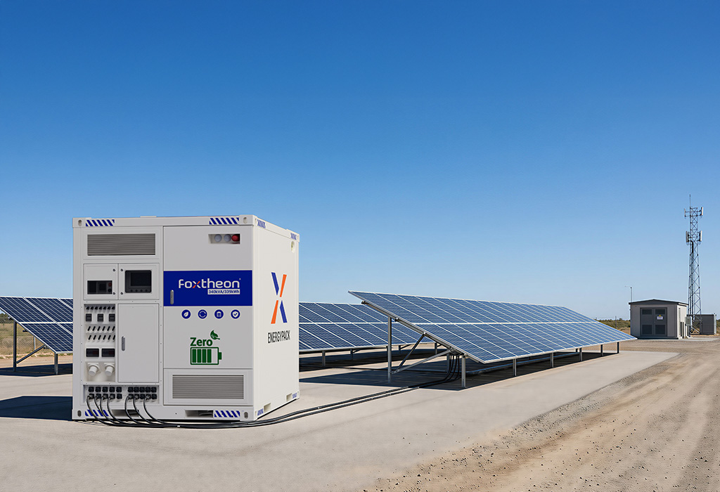
Remote industrial operations, such as deep-pit mining, remote telecommunications hubs, and isolated infrastructure construction sites, have historically relied on synchronous diesel generator sets (gen-sets) as their primary source of electrical energy. While these mechanical systems provide reliable baseline power, they face operational inefficiencies when subjected to highly variable load profiles. The integration of photovoltaic (PV) arrays and electrochemical energy storage systems presents a viable path toward optimizing these isolated networks. Among these advancements, the modern Solar Hybrid Generator represents a sophisticated, consolidated solution designed to bridge the gap between variable renewable generation and stable, continuous industrial power distribution.
To successfully integrate these systems, electrical engineers and microgrid designers must analyze the underlying power electronics, control topologies, and communication protocols. Industrial power solutions, such as those designed by Foxtheon, are engineered to coordinate multiple energy sources in real time, mitigating the power quality challenges inherent in off-grid operations.
1. System Architecture and Electrical Topologies
The fundamental topology of a high-power Solar Hybrid Generator comprises several distinct power conversion stages, safety systems, and control buses. Understanding the choice between DC-coupled and AC-coupled configurations is paramount during the front-end engineering design (FEED) phase.
DC-Coupled vs. AC-Coupled Topologies
In a DC-coupled architecture, the PV array and the battery energy storage system (BESS) are connected to a common DC bus. The solar generation is regulated via a Maximum Power Point Tracking (MPPT) buck-boost regulator that feeds directly into the DC link, which is also connected to the battery terminals through a bidirectional DC-DC converter. A centralized bi-directional Power Conversion System (PCS) then converts this DC voltage to AC to supply the site loads or synchronize with the diesel gen-set. This configuration exhibits higher round-trip efficiency for solar-to-battery charging, as it avoids unnecessary DC-AC and AC-DC conversion stages.
Conversely, AC-coupled topologies connect the PV inverter and the battery bi-directional inverter directly to the main AC bus. While this setup offers greater flexibility for retrofitting existing facilities with pre-installed solar infrastructure, it introduces multi-stage conversion losses and complicates phase synchronization and active power curtailment during low-load periods. For integrated, containerized systems, DC coupling is generally preferred due to its tighter control loops and minimized component count.
The Power Conversion System (PCS)
The PCS serves as the central bridge of the system. Operating in four quadrants, it regulates both active power (P) and reactive power (Q). Modern industrial units utilize Insulated Gate Bipolar Transistor (IGBT) or Silicon Carbide (SiC) semiconductor topologies with high-frequency switching to minimize Total Harmonic Distortion (THD) to less than 3% under linear loads. The PCS must support dual operating modes:
- Grid-Following (Current Source): The PCS synchronizes its output voltage and frequency with the reference signal established by an operating diesel gen-set.
- Grid-Forming (Voltage Source): The PCS establishes the voltage and frequency limits of the microgrid, acting as the slack bus and allowing the diesel gen-set to shut down completely during periods of high solar irradiance and sufficient battery State of Charge (SoC).
2. Advanced Control Logic and Operational Modes
The operational value of a Solar Hybrid Generator depends heavily on the firmware layer within its centralized Energy Management System (EMS). The EMS must monitor grid parameters, load demands, and battery health at millisecond intervals to execute complex state-machine transitions.
Genset Optimization and Wet-Stacking Mitigation
Diesel engines operated below 30% to 40% of their rated capacity suffer from incomplete fuel combustion, leading to carbon build-up on injector nozzles and exhaust valves—a condition known as wet-stacking. The control logic of the hybrid system addresses this by executing a load-leveling algorithm.
When the load drops below the gen-set’s minimum efficient threshold, the PCS transitions into a battery-charging state, artificially load-banking the gen-set to keep its operating point within the optimal 70% to 80% range of its fuel curve. Once the battery reaches a predefined high-limit SoC, the EMS commands the gen-set to initiate its cool-down cycle and shut down, transferring the entire load seamlessly to the battery-inverter system.
Hysteresis Loop and State-of-Charge (SoC) Management
To prevent premature battery degradation and system instability, the EMS utilizes a hysteresis loop for battery state-of-charge management. If a system is configured to cycle the battery between 20% and 90% SoC, the start/stop triggers for the auxiliary gen-set must be carefully tuned:
| System State | SoC Trigger Point | EMS Command Action | Electrical Response |
|---|---|---|---|
| Normal Discharge | > 35% | Inverter Mode Active | Batteries support load; solar charges via DC-DC. |
| Low-SoC Warning | 30% | Initiate Generator Start Signal | Dry contacts close; gen-set begins warm-up. |
| Generator Charge | 20% – 85% | Enable PCS Rectifier Mode | Gen-set supports load and charges battery at 0.5C rate. |
| Charge Termination | 85% | Disable PCS Rectifier Mode | Gen-set returns to idle/cool-down; inverter takes over. |
This hysteresis prevents the gen-set from short-cycling—a scenario where high frequency start-stop sequences cause excessive mechanical wear and fuel consumption.
3. Addressing Remote Industrial Engineering Pain Points
Remote industrial projects introduce harsh environmental and electrical challenges that standard commercial power solutions cannot withstand. Deploying a ruggedized Solar Hybrid Generator directly targets these systemic vulnerabilities.
Mitigating Transient Surges and Inductive Load Inrush
Industrial equipment, such as heavy-duty ventilation fans, submersible water pumps, and crushers, draws high inrush currents during start-up—often 6 to 8 times their nominal running current. Traditional diesel generators must be significantly oversized simply to ride through these transient spikes, leading to inefficient low-load operation during normal run-time.
By integrating a Solar Hybrid Generator alongside the diesel unit, the battery-powered PCS can deliver instantaneous power during transient startup phases. The high-discharge capability of Lithium Iron Phosphate (LFP) battery chemistries, combined with the sub-millisecond response time of bi-directional inverters, allows the system to inject active and reactive power during the first few cycles of the motor start-up. This active dampening prevents voltage sags and frequency deviation, protecting sensitive controls and telemetry equipment throughout the site network.
Power Quality and Harmonic Control in Harsh Environments
Non-linear loads, such as Variable Frequency Drives (VFDs) and switched-mode power supplies, introduce significant harmonic distortion into remote microgrids. This distortion can lead to overheating in synchronous generator windings, nuisance tripping of protective relays, and communication failures.
To maintain power quality under these conditions, the hybrid system’s PCS is engineered with active power filtering (APF) capabilities. By sensing the current waveform at the point of common coupling, the inverter can inject compensating harmonic currents, effectively neutralizing 5th, 7th, and 11th order harmonics and maintaining voltage THD within IEEE 519 standards.
Furthermore, remote operations often suffer from poor power factors. The EMS can dynamically allocate a portion of the PCS’s capacity to provide localized VAR compensation. This reduces the reactive power demand on the diesel generator, allowing it to run cooler and operate at a higher real-power output factor.
For operations utilizing remote assets, specialized systems such as those engineered by Foxtheon incorporate advanced thermal management systems—such as direct liquid cooling or climate-controlled IP54 enclosures—ensuring that the power electronics and battery cells remain within their optimal operating temperature range, even when ambient temperatures exceed 50°C in desert environments or fall below -20°C in high-altitude mining applications.
4. Communication Protocols and System Integration
For a hybrid system to operate reliably in an industrial setting, seamless integration with existing Supervisory Control and Data Acquisition (SCADA) platforms and diesel engine control units (ECUs) is required. This integration is achieved through standardized, industrial-grade communication networks.
The central controller typically employs Modbus TCP/IP or Modbus RTU over RS-485 interfaces to pull telemetry from the battery BMS, solar MPPT units, and branch circuit monitoring systems. Crucially, communication with the diesel gen-set’s digital controller (such as Deep Sea Electronics, ComAp, or Woodward controllers) is established via CAN bus utilizing the SAE J1939 protocol. This high-speed link allows the hybrid system to monitor engine speed, coolant temperature, oil pressure, and generator winding temperatures in real time.
If the microgrid requires rapid load shedding or black-start coordination, hardwired analog and digital I/O lines are used as high-reliability redundant paths alongside the digital bus. This prevents system-wide outages in the event of a localized communication bus failure, ensuring that the critical protective relays operate autonomously based on local voltage and frequency measurements.
5. Engineering Consultation and Project Integration
Implementing an off-grid power solution requires a thorough understanding of site-specific load profiles, environmental conditions, and existing generator assets. Rather than relying on standard, pre-packaged equipment, system integrators and procurement directors should perform detailed load profiling and transient analysis during the system design phase.
Engineering teams at Foxtheon are available to assist in analyzing your site’s operational parameters, including peak load requirements, average daily base loads, solar irradiance data, and harmonic profiles. By evaluating these parameters, our application engineers can provide customized single-line diagrams (SLDs), communication topology maps, and battery degradation modeling to ensure the integrated system meets your specific power reliability demands.
To discuss your project parameters with a technical specialist or to request a detailed engineering proposal, please contact our system design department directly.
Frequently Asked Questions
Q1: How does a Solar Hybrid Generator manage the synchronization process between the battery inverter and an online diesel generator?
A1: Synchronization is managed by the bi-directional PCS operating in grid-following mode. When the EMS commands the diesel gen-set to start, the generator’s Automatic Voltage Regulator (AVR) and speed governor establish the initial voltage and frequency on the AC bus. The PCS monitors this bus via voltage sensing transformers. Utilizing a Phase-Locked Loop (PLL) algorithm, the PCS aligns its output voltage, frequency, and phase angle with the generator’s waveform. Once synchronization parameters are met within millisecond tolerances, the PCS closes its output contactor, allowing both systems to support the load in parallel without circulating currents.
Q2: What protective measures are implemented in the battery system to prevent thermal runaway in high-temperature environments?
A2: The system features a multi-tiered safety architecture. At the cell level, we utilize Lithium Iron Phosphate (LFP) chemistry, which inherently possesses a high thermal runaway threshold (around 270°C) compared to other lithium chemistries. The Battery Management System (BMS) continuously monitors voltage and temperature at the individual cell and module levels. If a temperature sensor exceeds a warning threshold (typically 45°C), the BMS triggers auxiliary cooling systems. If the temperature continues to rise to a critical limit (typically 55°C), the BMS communicates with the central controller to derate the charging/discharging current. If safety limits are breached, the main DC contactors are opened mechanically to isolate the battery bank.
Q3: Can a Solar Hybrid Generator operate in a pure-island mode without any diesel generator connected?
A3: Yes, the system can operate in a pure-island configuration. In this scenario, the PCS is configured to operate in grid-forming mode, acting as the primary voltage source for the microgrid. It establishes a stable 50Hz or 60Hz sinusoidal voltage waveform and acts as the slack bus, absorbing or injecting power to balance instantaneous load changes. Under this mode, the solar MPPT controllers regulate their output based on the battery’s state of charge and the real-time load requirements, utilizing droop control frequency adjustment to curtail solar output if the load drops while the battery is fully charged.
Q4: How does the system handle highly unbalanced three-phase loads, which are common on construction sites?
A4: Modern industrial-grade hybrid systems utilize split-phase or three-phase split-phase inverter topologies with independent phase control. The bi-directional PCS is capable of handling up to 100% load unbalance across the three phases. By utilizing independent H-bridge inverter configurations for each phase and a robust neutral path, the controller dynamically adjusts the pulse-width modulation (PWM) duty cycle of each phase in real time. This maintains voltage phase displacement close to 120 degrees and keeps voltage phase deviation within acceptable limits, preventing phase-to-phase voltage imbalances from damaging sensitive three-phase motors.
Q5: What communication protocols are supported for integration with third-party SCADA and PLC networks?
A5: The system integrates with external industrial control networks through several standard protocols. The primary communication gateway supports Modbus TCP/IP over Ethernet and Modbus RTU over RS-485 for connection to PLCs, HMIs, and SCADA databases. For connection to utility-scale management systems or distributed energy resource managers (DERMS), the controller can be configured to support DNP3 or IEC 61850. Internally, high-speed CAN bus (J1939) is utilized for communication with the generator’s ECU, ensuring that protective alarms, engine speeds, and critical diagnostic parameters are shared without delay.