
.jpg)
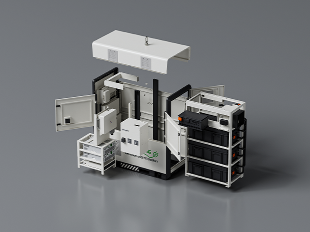
Commercial and industrial utility billing structures are dominated by two distinct metrics: cumulative volumetric consumption measured in kilowatt-hours (kWh) and peak power draw measured in kilowatts (kW) or kilovolt-amperes (kVA). The peak demand charge often accounts for thirty to fifty percent of an industrial facility’s electricity invoice. Deploying a dedicated peak shaving battery allows facility operators to clamp peak electrical draws beneath pre-established utility thresholds. Rather than consuming power from the grid during high-tariff, high-load intervals, the stationary storage system injects stored energy locally, flattening the demand profile observed by utility metering infrastructure.
Implementing stationary storage for peak reduction requires an engineering evaluation of the facility’s instantaneous load profile, the dynamic characteristics of electrical loads, and the thermal properties of battery chemistries. This technical analysis provides an evaluation of electrochemistry considerations, power conversion technologies, dispatch algorithms, and the integration of battery hardware into existing industrial distribution networks.
The Physics of Demand Charges and Interval Measurement
Electric utilities calculate demand charges based on maximum average power recorded during short intervals, typically fifteen or thirty minutes, within a billing cycle. Modern digital utility meters use either fixed-block or rolling-window interval integration methods.
- Fixed-Block Integration: The meter measures energy consumption over predefined blocks of time (e.g., 12:00 to 12:15). The accumulated energy is divided by the interval duration to calculate the average kW. Peak demand is the single highest block recorded during the month.
- Rolling-Window (Sliding-Block) Integration: The calculation window shifts in smaller sub-intervals (such as five minutes), calculating an average over the preceding fifteen minutes. This method captures demand surges that straddle fixed-block boundaries, increasing recorded peaks.
- Coincident vs. Non-Coincident Peaks: Non-coincident demand charges apply to the absolute peak draw of the facility regardless of overall grid conditions. Coincident demand charges apply during system-wide peak periods designated by the regional transmission organization (RTO) or distribution system operator (DSO), such as Five Coincident Peak (5CP) frameworks.
- Ratchet Clauses: Many industrial utility contracts enforce minimum demand charges based on the maximum peak established within the previous eleven months, meaning a single 15-minute load spike can inflate utility billing for a full year.
Mitigating these peaks requires an energy storage resource capable of dispatching precisely when instantaneous demand approaches the established setpoint. The operational response time of an integrated peak shaving battery system must transition from standby to full discharge within milliseconds to prevent sub-interval spikes from registering on rolling-window billing meters.
Electrochemistry Topologies and Cell-Level Engineering
System architects must evaluate the underlying battery chemistry based on cycle life, dynamic C-rate capabilities, thermal runaway thresholds, and capacity retention under shallow-to-medium cycling conditions. Lithium Iron Phosphate (LiFePO4 or LFP) has become the dominant technology for commercial and industrial stationary storage, surpassing Nickel Manganese Cobalt (NMC) formulations in these stationary metrics.
Lithium Iron Phosphate (LFP) Characteristics
LFP chemistries provide an olivine crystal structure characterized by strong covalent P-O bonds. This structural stability provides resistance to oxygen release at elevated temperatures, preventing thermal runaway up to approximately 270 degrees Celsius. The electrochemical characteristics include:
- Nominal Cell Voltage: 3.2 V per cell, with an operating voltage window between 2.5 V and 3.65 V.
- Specific Energy: 140 to 175 Wh/kg at the cell level, which is lower than NMC but sufficient for stationary installations where footprint and weight are secondary to lifespan.
- Degradation Kinetics: Solid Electrolyte Interphase (SEI) growth on the graphite anode remains stable when operated within standard state-of-charge (SOC) ranges. High-quality LFP cells routinely deliver between 6,000 and 8,000 cycles at 80% Depth of Discharge (DoD) under 0.5C/0.5C operating regimes.
Thermal Management Architecture
The operational profile of a peak shaving asset involves short bursts of high current discharge (0.5C to 1C rates for durations ranging from 30 minutes to 2 hours), often followed by low-rate charging during off-peak windows. This operational cycle produces non-uniform internal heating within cell stacks.
Liquid cooling topologies have superseded forced-air convection in industrial energy storage systems. Liquid cold plates positioned along the wide faces of prismatic cells maintain intra-pack temperature deltas beneath 3 degrees Celsius. Maintaining low thermal variance across the string prevents individual cells from aging prematurely, which preserves string-level balancing and avoids usable capacity loss.
Power Conversion Systems (PCS) and Interconnection Topologies
The Power Conversion System (PCS) forms the bridge between the high-voltage direct current (DC) battery bus and the three-phase alternating current (AC) distribution system of the plant. A bi-directional, four-quadrant inverter architecture is necessary for simultaneous active (kW) and reactive (kVAR) power manipulation.
Coupling Architectures
Deployments are configured using either DC-coupled or AC-coupled topologies:
- AC-Coupled Systems: The battery and PCS are connected directly to the facility’s 480V or medium-voltage AC switchgear. This architecture isolates the storage system from onsite generation assets, making it suitable for retrofits. The storage asset functions as an independent, dispatchable sub-station.
- DC-Coupled Systems: The battery shares a common DC bus with distributed energy resources, such as commercial photovoltaic arrays, through DC-DC buck/boost converters before feeding into a central bidirectional inverter. While offering marginal efficiency improvements by eliminating a DC-AC-DC conversion step, DC-coupling complicates independent control of the storage asset during discrete grid events.
Advanced commercial platforms engineered by manufacturers like Foxtheon utilize modular AC-coupled architectures. This approach ensures that the energy storage subsystem operates without requiring redesigns of existing plant switchboards or downstream motor control centers.
Four-Quadrant Operation and Power Factor Management
Inductive industrial loads (such as large induction motors, transformers, and arc furnaces) pull reactive power, lowering the facility’s power factor. Many utilities impose penalties when power factor drops below 0.90 or 0.95. Modern PCS hardware modulates both real power ($P$) and reactive power ($Q$). By injecting leading reactive current during peak shaving operations, the system simultaneously suppresses demand charges and clears power factor penalty thresholds without dedicated capacitor banks.
Algorithmic Dispatch and EMS Control Strategies
Hardware capabilities depend directly on the Energy Management System (EMS) software directing them. An EMS managing a peak shaving battery relies on high-speed monitoring at the utility point of common coupling (PCC).
Static Threshold Shaving
The simplest control paradigm relies on fixed setpoint dispatch. The operator designates a hard power ceiling (e.g., 500 kW). Current transformers (CTs) and digital power transducers at the utility service entrance monitor net facility load at frequencies between 10 Hz and 50 Hz. When load crosses the 500 kW ceiling, the EMS commands the PCS to discharge power equal to the difference ($P_{discharge} = P_{load} – P_{threshold}$). While straightforward, static thresholds can deplete battery reserves prematurely if an atypical extended load event occurs early in the billing window.
Dynamic Model Predictive Control (MPC)
Advanced installations utilize dynamic algorithms combining historical consumption telemetry, localized production schedules, and forward-looking weather data. Dynamic MPC operates over a rolling optimization horizon:
- Load Forecasting: Neural networks or auto-regressive integrated moving average (ARIMA) models forecast facility consumption for the subsequent 24 to 48 hours.
- State-of-Charge Management: The EMS optimizes the battery’s dispatch window to ensure that reserves are not depleted prior to the true billing peak of the day.
- Tariff Arbitrage Alignment: The system identifies low-cost energy windows to restore SOC, managing charging currents to avoid introducing a secondary, charging-induced peak on the facility’s load profile.
System Sizing Metrics: C-Rate, Duration, and Capacity
Dimensioning an industrial storage project requires balancing capacity (kWh) and power rating (kW). Over-sizing capital assets ties up space and capital, while under-sizing exposes the facility to unmitigated demand spikes.
Discharge Duration and C-Rate Selection
The ratio of energy capacity to power output defines the discharge duration of the installation ($t = E / P$). Most peak shaving battery applications require durations between one and four hours (corresponding to discharge rates between 1C and 0.25C):
- 1-Hour Systems (1C): Suited for sharp, short-duration load spikes, such as crane lifting cycles or batch manufacturing process startups.
- 2-Hour Systems (0.5C): The benchmark configuration for commercial facilities with broad plateau profiles, such as HVAC-driven summer cooling peaks.
- 4-Hour Systems (0.25C): Deployed in utility territories with broad coincident peak programs (e.g., peak demand pricing windows spanning four consecutive afternoon hours).
Degradation Allowance and Oversizing
A battery cell degrades over calendar time and operational cycling. The usable capacity diminishes as lithium inventory becomes immobilized within the SEI layer. Sizing models must incorporate an End-of-Life (EOL) capacity retention factor, typically set at 70% or 80% of original capacity after 10 to 15 years. An installation requiring 200 kW of power delivery for two hours (400 kWh usable) must be commissioned with an initial capacity of approximately 500 kWh nameplate capacity to maintain system setpoints throughout its operational lifecycle.
Integration Alongside Existing Plant Infrastructure
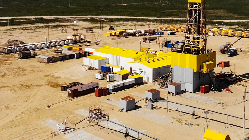
Industrial facilities rarely operate on battery storage alone; they feature complex electrical distribution topologies incorporating legacy power generation, unscheduled motor loads, variable frequency drives (VFDs), and standby generator assets.
Hybrid Synergy with Standby Generators
A common configuration involves operating a peak shaving battery alongside existing emergency diesel or natural gas generators. These existing generation assets are engineered for primary emergency backup during extended utility outages rather than frequent cycling for tariff management. Starting a heavy combustion engine to mitigate a brief 20-minute demand surge introduces mechanical wear, cold-start inefficiencies, and localized emissions permits issues.
The battery system functions as the dynamic first responder. It absorbs instantaneous demand variations and manages peak tariff spikes without requiring generator startup. When prolonged outages occur, the battery can stabilize microgrid voltage and frequency while the rotary assets start up, synchronize, and ramp up to steady-state loading.
Protection Coordination and Arc Flash Mitigation
Integrating high-energy storage systems into an industrial switchboard alters short-circuit current contributions. Battery systems have lower short-circuit currents than rotational machines of equivalent rating, governed strictly by the PCS semiconductor limits (typically 1.1x to 1.5x nominal current). The facility’s protection scheme must account for these dynamics:
- Fast-Acting Semiconductor Fuses: Installed at the DC string level and the AC inverter output to isolate faults within milliseconds, protecting the silicon IGBTs or SiC MOSFETs.
- Directional Overcurrent Relays: Placed at the interconnect bus to distinguish between upstream grid faults and internal distribution faults.
- Arc Flash Studies: Re-calculating the incident energy at the point of connection to verify that electrical enclosures maintain proper National Electrical Code (NEC) and NFPA 70E safety ratings.
Sourcing Considerations and Manufacturing Standards
Selecting reliable suppliers for industrial-grade systems requires rigorous evaluation of quality management protocols, cell tiering, and compliance with international standards. Manufacturers like Foxtheon align engineering specifications with stringent international safety and reliability codes.
Regulatory Compliance Matrix
Equipment procurement matrices should verify the following certifications:
- UL 1973: Tests the safety of battery packs for use in stationary applications, evaluating mechanical impact, electrical abuse, and environmental durability.
- UL 9540: Evaluates the complete, integrated energy storage system (combining cells, PCS, thermal management, and fire suppression).
- UL 9540A: Standard test method for evaluating thermal runaway fire propagation in battery energy storage systems. Tier-one suppliers must provide full UL 9540A test reports demonstrating that thermal events do not propagate from cell to cell or rack to rack.
- IEC 62619: Specifies safety requirements for secondary lithium cells and batteries used in industrial stationary applications.
Supply Chain and Cell Traceability
Engineering audits of supplier manufacturing capabilities must evaluate cell sourcing origins. Tier-one installations demand complete traceability of cathode precursor materials, cleanroom automated assembly (Class 10,000 or better), and statistical process control (SPC) data across cell voltage, impedance matching, and weld integrity. Verifying these manufacturing standards ensures low self-discharge rates and uniform degradation across the battery string.
Industrial Peak Shaving Battery Systems: Common Questions
Q1: How does a peak shaving battery differ from a standard backup power system?
A1: While a backup system (like an uninterruptible power supply or emergency generator) remains dormant until a complete power interruption occurs, an industrial peak shaving battery operates dynamically on a daily basis. It synchronizes with the grid to inject power during periods of elevated consumption to lower measured demand charges, cycling frequently while staying connected to the active electrical bus.
Q2: Can peak shaving installations run simultaneously with onsite solar photovoltaics?
A2: Yes. Solar generation profiles often do not align with industrial facility consumption peaks. Integrating battery systems allows excess solar energy generated during midday to be stored and subsequently dispatched during late afternoon or evening facility demand spikes, maximizing self-consumption and clipping peaks that occur after sunset.
Q3: What is the standard response time of a peak shaving inverter system?
A3: Modern Power Conversion Systems utilizing insulated-gate bipolar transistors (IGBTs) or silicon carbide (SiC) switches feature full-power step response times under 20 milliseconds. This high-speed response ensures that step-load additions inside the facility (e.g., direct-on-line motor starts) are absorbed by the battery before utility metering equipment integrates the load spike into the interval average.
Q4: How does depth of discharge (DoD) impact battery service life in peak shaving duties?
A4: Cycle life is inversely proportional to Depth of Discharge. Peak shaving applications often require discharge depths between 40% and 70% rather than full 100% depletion cycles. Restricting the operational DoD range minimizes mechanical strain inside the LFP crystal matrix, extending functional life beyond 6,000 to 8,000 cycles under appropriate thermal conditions.
Q5: Does adding an energy storage system require modifications to utility interconnection agreements?
A5: In most jurisdictions, adding a grid-parallel stationary battery requires an interconnection study and an updated agreement with the local utility. Even if the system is configured for non-export operation (zero export to the utility grid via reverse-power relays), safety protocols require review by the utility engineer to ensure proper anti-islanding protection and fault-contribution compliance.
Technical Project Inquiries and System Specification Support
Sizing and integrating a multi-megawatt-hour or multi-hundred-kilowatt storage solution requires rigorous facility interval data analysis and switchgear integration engineering. For direct technical inquiries regarding equipment sizing, PCS integration parameters, liquid cooling configurations, and utility interconnect modeling, contact the application engineering team at Foxtheon via their engineering services portal:
Technical Inquiries: https://www.foxtheon.com/