

Grid edge modernization requires resilient, responsive energy storage infrastructures capable of handling rapid power fluctuations, harmonic distortion, and intermittent generation profiles. Specifying a utility or commercial-scale battery storage system demands a rigorous evaluation of electrochemistry, power conversion topologies, thermal containment boundaries, and automated control systems. This technical analysis outlines the multi-layered engineering disciplines required to evaluate, implement, and maintain industrial energy storage assets.
Electrochemical Foundations and Lithium Iron Phosphate Mechanics
Utility-grade stationary storage predominantly utilizes Lithium Iron Phosphate (LiFePO4 or LFP) chemistry over Nickel Manganese Cobalt (NMC) chemistries due to intrinsic thermodynamic stability. The olivine crystal structure of LFP features robust P-O covalent bonds that prevent oxygen release at elevated operational temperatures, effectively mitigating internal cell thermal events up to 270°C.
When selecting cell formats for long-duration stationary applications, prismatic aluminum-cased cells offer higher structural integrity and volumetric efficiency compared to cylindrical or pouch equivalents. Key electrochemical parameters include:
- Nominal Cell Voltage: 3.2V per cell, operating within a standard window of 2.5V (discharge cutoff) to 3.65V (charge cutoff).
- Cycle Life Degradation: Retention of ≥80% State of Health (SOH) after 6,000 to 8,000 full cycles at 0.5C/0.5C charge/discharge rates under 25°C baseline conditions.
- Solid Electrolyte Interphase (SEI) Stability: Controlled electrolyte decomposition during initial formation cycles, which prevents continuous lithium inventory loss during low-temperature charging.
- Coulombic Efficiency: Exceeding 99% under standardized test conditions, minimizing internal parasitic losses during high-frequency throughput cycling.
Rack-Level Architecture and Battery Management System (BMS) Topologies
Modern industrial installations configure cells into modular series-parallel strings to generate DC bus voltages ranging from 800V DC to 1500V DC. Higher DC bus voltages significantly reduce transmission current, which minimizes resistive I²R thermal losses across internal busbars and reduces required cabling cross-sections.
A resilient multi-tiered Battery Management System architecture consists of three hierarchical layers:
- Cell Monitoring Units (Slave BMS): Directly attached to module busbars to sample individual cell voltage (±1mV precision) and surface temperature via Negative Temperature Coefficient (NTC) thermistors at millisecond intervals.
- Rack Management Units (Master BMS): Aggregates serial strings, monitors total string current via Hall-effect transducers or high-precision shunt resistors, and calculates real-time State of Charge (SOC) using Extended Kalman Filtering (EKF) to compensate for ampere-hour integration drift.
- System Array Controller: Communicates across all rack controllers through dual-redundant CAN bus 2.0B or Modbus TCP/IP protocols to execute active balancing, contactor sequencing, and rack-level isolation monitoring.
Active balancing circuitry redistributes charge from higher-capacity cells to lower-capacity cells using bidirectional inductive or capacitive converters, maintaining a maximum intra-rack voltage delta of less than 20mV without generating the thermal dissipation associated with passive resistor bleeding.
Thermal Management Topologies: Liquid Cooling versus Forced Air
Thermal variance within a battery enclosure directly accelerates localized degradation rates. A temperature discrepancy exceeding 3°C between cells within the same string leads to premature capacity loss and uneven impedance growth. Consequently, high-density installations rely on closed-loop liquid cooling instead of forced-air HVAC circulation.
Liquid thermal regulation employs cold-plate heat exchangers constructed from extruded aluminum channels placed directly beneath or between cell groupings. A 50/50 ethylene glycol and demineralized water mixture circulates through the closed loop, maintaining operating fluid velocity between 0.5 to 1.5 m/s. This configuration achieves superior heat transfer coefficients compared to air, keeping cell junction temperatures strictly within the optimal 20°C to 28°C range even during continuous 1C discharge profiles.
Systems engineered by Foxtheon integrate dynamic variable-speed pump controllers and electronic expansion valves. These components adjust coolant flow rates in direct response to predictive thermal modeling data supplied by the central BMS, maintaining internal thermal equilibrium across varying ambient environments.
Power Conversion Systems (PCS) and Four-Quadrant Grid Support
The bidirectional Power Conversion System serves as the electrical transmission interface between the DC battery racks and the medium-voltage AC distribution infrastructure. Modern installations utilize Silicon Carbide (SiC) MOSFET or Insulated Gate Bipolar Transistor (IGBT) three-level neutral-point clamped (NPC) inverter topologies, achieving conversion efficiencies above 98.5%.
The PCS must execute four-quadrant active (P) and reactive (Q) power control as defined by IEEE standards for interconnection:
- Active Power Modulation: Rapid power injection or absorption within sub-20ms timeframes to provide primary frequency response and fast frequency reserves (FFR).
- Reactive Power Compensation: Continuous STATCOM-like functionality, supplying leading or lagging VARs to stabilize local bus voltage independent of the battery’s active energy dispatch state.
- Harmonic Mitigation: Active power filtering suppressing Total Harmonic Distortion (THD) of current to under 3% at rated power, meeting strict grid code interconnect requirements.
Microgrid Asset Synthesis: Operating Alongside Existing Generation Infrastructure
Integrating a modern battery storage system alongside existing thermal generation assets, such as diesel or reciprocating natural gas gensets, dramatically improves overall plant heat rate and system stability. Traditional thermal engines suffer from severe fuel inefficiency and increased maintenance overhead when forced to run at low partial-load conditions to handle sudden dynamic peaks.
Deploying energy storage in a hybrid configuration provides instantaneous synthetic inertia and spinning reserve coverage. The battery absorbs step loads within milliseconds, allowing thermal generators to ramp up smoothly along their optimal Brake Specific Fuel Consumption (BSFC) curves without causing system frequency drops. Furthermore, during periods of surplus clean power or light loads, the storage array can absorb generation excess, enabling internal combustion assets to operate strictly within their peak efficiency bands (typically 75% to 85% continuous loading).
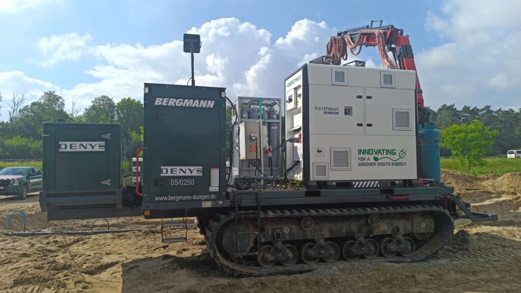
Advanced hybridization architectures engineered by Foxtheon leverage intelligent microgrid controllers that execute sub-cycle synchronization between legacy switchgear, renewable inputs, and storage blocks, establishing a highly stable localized electrical balance without requiring the decommissioning of functional generation infrastructure.
Energy Management Systems (EMS) and Autonomous Dispatch Algorithms
The Energy Management System provides supervisory monitoring and automated scheduling over the complete facility footprint. Communication with plant Supervisory Control and Data Acquisition (SCADA) platforms is executed via standardized protocols including IEC 61850, Modbus TCP, and DNP3.
Deterministic algorithms implemented within the EMS optimize daily cycling through several distinct operational modes:
- Dynamic Peak Shaving: Continuously monitoring utility demarcation power meters and discharging the storage system within 50ms of detecting power draw above pre-configured threshold setpoints, thereby mitigating grid demand penalties.
- Load Shifting and Price Arbitrage: Automatically charging the system during low-tariff, off-peak hours and discharging stored power during maximum tariff windows according to programmed utility pricing matrices.
- Microgrid Islanding Transition: Executing seamless, uninterrupted transfers between grid-connected and islanded operation modes using grid-forming inverter controls that emulate physical rotational mass via synthetic droop characteristics.
Safety Engineering, Gas Detection, and Regulatory Compliance
Industrial battery installations require multilayered life safety and containment systems governed by international codes, including NFPA 855 and standards defined by the International Electrotechnical Commission (IEC). System developers must engineer enclosures to contain and vent off-gassing products long before thermal thresholds are exceeded.
Early-stage detection utilizes multi-sensor detection arrays that combine optical smoke detection, hydrogen (H2) sniffers, and non-dispersive infrared (NDIR) carbon monoxide (CO) detectors. Because battery off-gassing emits significant volumes of hydrogen, carbon monoxide, and hydrocarbon gases during cell venting, these sensors trigger secondary protection stages before smoke or open flames develop:
- Automated high-speed circuit interrupters separate the DC bus disconnects, isolating faulty modules electrically.
- High-volume explosive gas exhaust fans activate, maintaining internal enclosure atmospheres well below 25% of the Lower Explosive Limit (LEL).
- Specialized aerosol or clean agent gaseous fire suppression systems deploy to extinguish peripheral flare-ups, while continuous dry-pipe deluge systems provide direct structural cooling if required.
Validation of system containment relies heavily on the UL 9540A large-scale fire test methodology, which provides empirical data on heat release rates, flammability limits, and inter-rack thermal runaway propagation boundaries.
Technical Specification and Manufacturer Evaluation Matrix
When issuing a technical Request for Proposal (RFP) for a high-voltage battery storage system, procurement and engineering teams must evaluate detailed technical metrics that go beyond basic nameplate capacity ratings:
- Round-Trip Efficiency (RTE): Demanding AC-to-AC RTE figures of ≥86% measured at the MV transformer secondary terminals, inclusive of all parasitic auxiliary loads (HVAC, pumps, controls).
- Degradation Warranties: Ensuring contractual capacity guarantees incorporate specific cyclic operational boundaries, throughput quotas (e.g., MWh processed per rack), and ambient temperature boundary envelopes.
- Short-Circuit Withstand Ratings: Verifying that DC busbar assemblies, high-speed DC fuses, and motorized breaker units maintain coordinated interrupting capacities matching the maximum potential prospective fault currents calculated for parallel strings.
- Container Structural Integrity: Enclosures must feature minimum IP54 or NEMA 3R weather protection, C5 anti-corrosion marine-grade surface coatings, and seismic rating qualifications up to Zone 4 conditions.
Frequently Asked Questions
Q1: What are the main electrical differences between grid-following and grid-forming inverters in stationary storage?
A1: Grid-following inverters require a stable, external AC voltage and frequency reference provided by the utility or local generators to synchronize their current injection. In contrast, grid-forming inverters establish their own independent voltage and frequency source, utilizing virtual synchronous machine algorithms to generate stable AC waveforms during black starts or microgrid islanding scenarios.
Q2: How does dynamic internal impedance correlate with battery degradation over time?
A2: As an electrochemical cell undergoes repeated charge and discharge cycles, the degradation of active electrode materials and the thickening of the solid electrolyte interphase (SEI) layer increase internal DC resistance (ESR). Higher internal impedance causes elevated operating temperatures and increased voltage drops during high-current discharges, ultimately reducing accessible nameplate capacity.
Q3: Why is high-voltage (1500V DC) architecture preferred over traditional 1000V DC designs in industrial projects?
A3: Operating at 1500V DC allows for an increase in total power throughput without raising current levels. This enables engineers to use smaller cable diameters, reduce the number of inverter inputs, consolidate balance-of-plant switchgear, and reduce thermal conduction losses, leading to higher overall operational efficiency.
Q4: How do commercial sites combine thermal generation assets with a battery storage system without causing phase instability?
A4: Integration is managed via centralized digital controllers using high-speed communication interfaces (such as fiber-optic Ethernet). The storage system provides instantaneous power to suppress high-frequency load transients, allowing the mechanical governors and excitation systems of thermal generators to adjust gradually without crossing phase margin thresholds or experiencing mechanical stress.
Q5: What key metrics determine whether a system requires liquid cooling over forced-air thermal management?
A5: System continuous C-rate, enclosure volumetric energy density, and geographic ambient temperature profiles are the primary indicators. Installations handling steady charge and discharge cycles of 0.5C or greater, or installations situated in ambient environments routinely exceeding 35°C, necessitate liquid thermal solutions to maintain internal cell temperature spreads within the mandated ±2°C limit.
Technical Specification Inquiry
Engineering and procurement teams seeking site-specific technical evaluations, electrical schematics, and integration parameters for commercial, industrial, or microgrid deployments may submit their single-line diagrams (SLD) and load demand profiles directly to our systems engineering group. Inquire directly through Foxtheon engineering support at battery storage system integration services.