
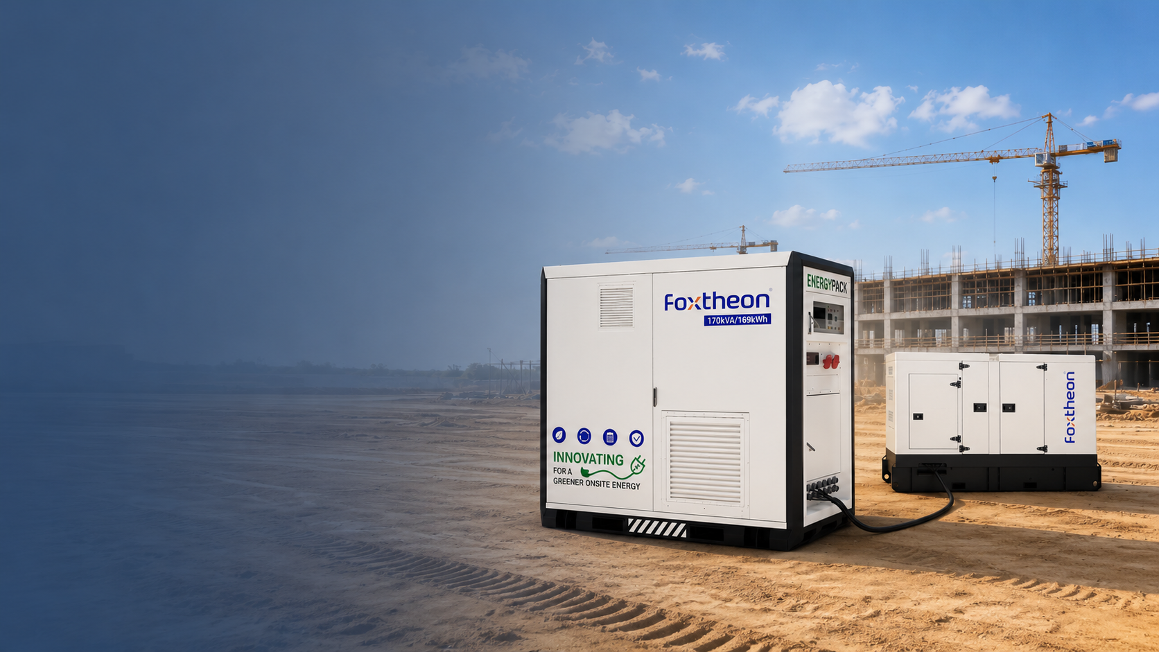
Commercial and industrial facilities require continuous, high-grade power delivery while operating within increasingly complex regulatory and electrical environments. The application of a solar hybrid battery system addresses these demands by bridging variable photovoltaic generation with dispatchable energy storage and on-site generation infrastructure. Rather than functioning as an isolated component, modern storage engineering incorporates multi-port power conversion, advanced thermal modeling, and algorithmic controls to optimize power flow across diverse industrial assets.
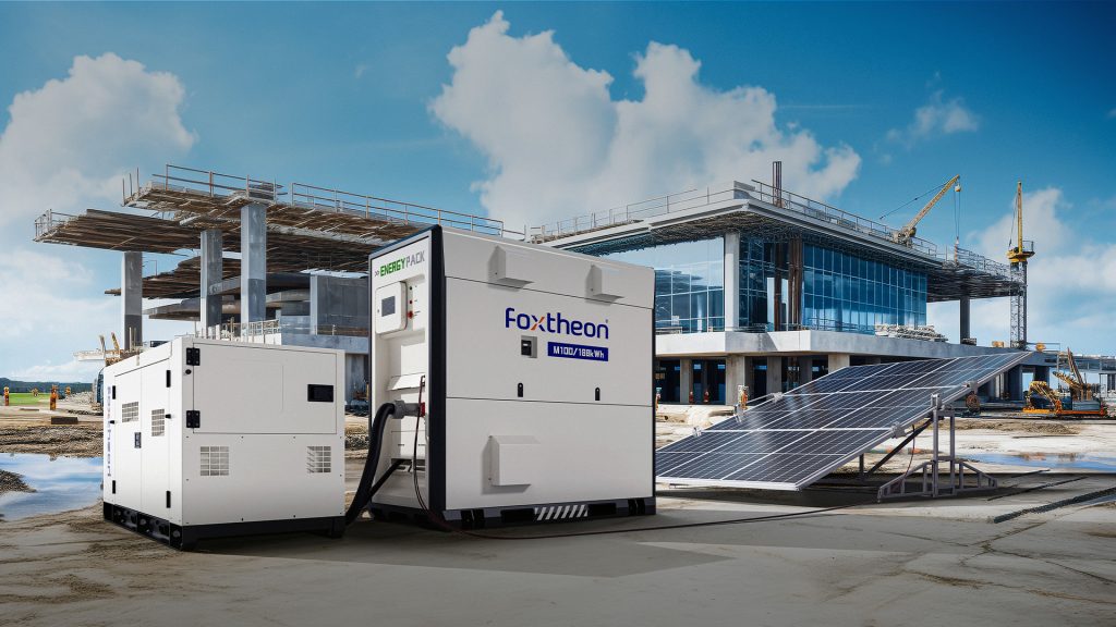
1. System Topologies: DC-Coupled vs. AC-Coupled Architectures
The core configuration of an industrial energy storage deployment depends on the coupling topology chosen during front-end engineering design. Both direct-current (DC) and alternating-current (AC) coupling present distinct mechanical, electrical, and thermal trade-offs.
DC-Coupled Architecture
In a DC-coupled configuration, the photovoltaic array and the electrochemical storage subsystem connect to a shared direct-current bus. This bus interfaces with a central bidirectional inverter that feeds the alternating-current distribution panel.
- Conversion Efficiency: Solar generation charges the cells directly via a DC-to-DC buck/boost regulator with maximum power point tracking (MPPT). This pathway avoids the DC-AC-DC double-conversion losses inherent in distributed configurations, maintaining electrical round-trip efficiencies typically between 94% and 97%.
- Clipping Energy Recapture: When photovoltaic production exceeds the power conversion system (PCS) nominal AC nameplate rating, surplus energy flows directly into the electrochemical cells rather than being lost to inverter clipping.
- System Constraints: Centralizing the DC bus requires precise voltage matching. The string design must operate within the continuous DC voltage window of the common converter, complicating retrofit applications where existing PV inverters are already commissioned.
AC-Coupled Architecture
AC-coupled systems locate the PV inverter and the battery bi-directional inverter on a common alternating-current bus. This structure is prevalent in facility expansions where solar installations already operate under utility interconnection agreements.
- Integration Flexibility: Storage blocks can be placed independently of existing solar arrays, minimizing civil trenching and high-voltage DC runs over extended facility footprints.
- Fault Isolation: Because each conversion system operates autonomously via standard distribution switchgear, issues within the PV conversion train do not inhibit the storage system’s ability to provide local power conditioning or support facility loads.
- Conversion Losses: Energy generated by the solar array must undergo DC-AC inversion, AC-DC rectification to store, and subsequent DC-AC inversion to discharge, resulting in an accumulated round-trip efficiency loss of approximately 8% to 12% across the cycle.
2. Cell Chemistry and Mechanical Construction
Industrial storage systems rely primarily on lithium-ion technologies, with Lithium Iron Phosphate (LiFePO4 or LFP) serving as the baseline chemistry for stationary applications, contrasted with Nickel Manganese Cobalt (NMC) variants in specific footprint-constrained scenarios.
LFP demonstrates chemical stability due to the strong covalent bonds between iron, phosphorus, and oxygen atoms in its olivine crystal structure. This configuration resists oxygen release under elevated temperatures, setting the thermal runaway threshold above 270°C. In comparison, layered NMC structures typically initiate exothermic degradation between 200°C and 220°C. Consequently, commercial procurement prioritizes LFP for safety certification under UL 9540A testing procedures.
Cell form factors also dictate packaging density, heat rejection capabilities, and longevity:
- Prismatic Cells: Enclosed in rigid aluminum or welded steel cans, prismatic cells offer structural integrity and predictable mechanical tolerance under thermal expansion. Their broad surfaces allow for direct integration with aluminum liquid cooling plates, reducing cell-to-cell thermal gradients across deep charge-discharge profiles.
- Pouch Cells: While offering higher gravimetric energy density, pouch cells require external clamping fixtures to mitigate mechanical swelling during repeated lithiation and delithiation cycles. Internal pressure variations can yield uneven degradation across the active electrode surface.
- C-Rate Characteristics: Industrial applications typically specify continuous charge and discharge rates between 0.5C and 1C. Operating within this envelope preserves cathode microstructure, allowing systems to reliably achieve 6,000 to 8,000 equivalent full cycles at 80% Depth of Discharge (DoD).
3. Grid Interconnect and Dispatch Modes
A sophisticated solar hybrid battery operates across several operational modes determined by internal telemetry, switchgear status, and supervisory control systems.
Peak Shaving and Demand Management
Industrial utility tariffs frequently penalize facilities based on the maximum 15-minute average demand window within a billing cycle. The integrated storage platform continuously measures incoming line currents via fast-response current transformers (CTs). When plant loads surpass a preset kW threshold, the battery conversion system injects active power within milliseconds, effectively plateauing the utility demand curve without interrupting operations.
Microgrid Islanding and Black Start Operation
Upon detection of abnormal voltage or frequency deviations at the point of common coupling (PCC), an intelligent static transfer switch (STS) mechanically isolates the internal distribution bus from the grid within 10 to 20 milliseconds. Operating in grid-forming mode, the power conversion system establishes a local voltage and frequency reference. This black-start capability allows the microgrid to energize downstream transformers and balance fluctuating local loads alongside intermittent solar output.
4. Harmonization with Existing Generator Assets
Rather than seeking to displace conventional generation fleets, modern distributed control systems prioritize coordinated operation. Industrial sites frequently run diesel or natural gas generation sets to supply baseline energy under utility disruptions or remote microgrid conditions.
Direct integration of a solar hybrid battery with thermal generator sets addresses several mechanical and thermodynamic operational limitations:
- Mitigating Wet Stacking: Internal combustion engines operate poorly under low loading (below 30% to 40% of rated capacity), resulting in unburned fuel accumulating in the exhaust manifold—a condition known as wet stacking. The battery system absorbs excess generation or injects dynamic power to maintain the engine’s loading within its optimal brake-specific fuel consumption (BSFC) island.
- Spinning Reserve Replacement: Facilities often keep surplus generators idling to cover unexpected motor inrush or momentary drops in solar generation. Utilizing high-response electrochemical storage to handle dynamic step-loads allows operators to shut down redundant thermal units, running only the exact generation assets required for steady-state demand.
- Harmonic Suppression: Heavy non-linear industrial loads introduce significant Total Harmonic Distortion (THD) into isolated microgrid buses. Active power conversion systems actively inject anti-phase currents to cancel lower-order harmonics, shielding rotating generators from rotor overheating and stator winding stresses.
Manufacturers like Foxtheon develop balance-of-plant interfaces specifically configured to communicate across legacy generator controller networks, supporting coordinated operational profiles without requiring the replacement of commissioned assets.
5. Battery Management Architecture and Control Layers
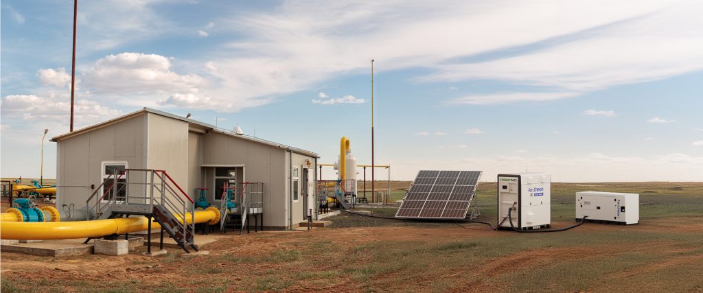
Reliable operation of multi-megawatt-hour systems relies on a hierarchical management structure that spans individual cell electronics up to cloud-connected orchestration platforms.
Three-Tier Battery Management System (BMS)
The control topology is systematically distributed:
- Tier 1 (Module Level): Slave boards monitor individual cell metrics, including surface temperatures via NTC thermistors and millivolt-level cell potentials. Dynamic passive or active balancing circuits redistribute or dissipate energy to keep individual cell parameters aligned across the string.
- Tier 2 (Rack Level): Master control units aggregate data from multiple modules, calculating overall rack State of Charge (SoC), State of Health (SoH), and internal resistance. High-voltage contactors, DC fuses, and pyrofuses are actuated at this layer in response to over-voltage, under-voltage, or thermal divergence.
- Tier 3 (System Level): The central BMS interfaces with all rack managers, resolving current-sharing disparities across parallel strings and maintaining communication with the external Power Conversion System via high-speed Controller Area Network (CAN bus) or Modbus TCP protocols.
Energy Management System (EMS) and Analytics
The supervisory EMS executes high-level optimization algorithms. By processing live load telemetry, historical consumption profiles, and solar irradiation forecasts, the EMS coordinates charging schedules to maximize on-site solar consumption while minimizing thermal degradation cycles.
6. Thermal Management: Air Cooling vs. Liquid Cooling
Temperature variation across an energy storage container accelerates localized aging, leading to impedance mismatches between parallel strings. Industrial systems employ two primary heat dissipation designs.
Forced-Air Thermal Architecture
Forced-air designs use high-capacity HVAC units to drive conditioned air through dedicated ducting across the battery racks. While straightforward to maintain, air has a low volumetric heat capacity (approximately 1.2 kJ/m³K). Consequently, dense racks often develop localized thermal pockets, with cells positioned furthest from the plenum operating up to 5°C to 8°C warmer than intake cells. This thermal variation creates divergent internal resistances and uneven capacity fade over multi-year cycles.
Liquid-Cooled Plate Architecture
Liquid cooling utilizes an ethylene-glycol water mixture pumped through cold plates mounted directly to the bases or sides of prismatic cell modules. Liquid offers a volumetric heat capacity over 3,000 times greater than air. This mechanism enables precise thermal uniformity, holding cell-to-cell temperature differentials within 2°C to 3°C across high-stress charge and discharge cycles.
Liquid systems run at higher auxiliary efficiency because pumping fluid requires less auxiliary parasitic power than moving high-volume air through restrictive filters. Engineering solutions from Foxtheon utilize sealed, closed-loop liquid thermal controls to support steady continuous duty even in high ambient operating environments.
7. Engineering Challenges in Industrial Environments
Deploying energy storage within active industrial spaces introduces distinct engineering hurdles that require robust front-end mitigation.
Inrush Currents and Inductive Loads
Industrial machinery—such as heavy induction motors, chillers, and hydraulic presses—draws starting currents between five and eight times their continuous full-load amps. A solar hybrid battery inverter must feature substantial overload capacity (e.g., 150% to 200% for 10 to 30 seconds) or interface directly with variable frequency drives (VFDs) and soft-starters to prevent voltage sag trips during inductive load across-the-line starting.
Fault Current Contribution and Protection Coordination
Unlike synchronous generators that provide high sustained fault current (often 300% to 500% of nominal) to trip downstream thermal-magnetic circuit breakers, inverter-based resources are current-limited by their power semiconductors (typically 110% to 120% of rated current). Protection engineers must implement specialized relay schemes, such as zone-selective interlocking or microprocessor-based differential relays, to ensure faults are isolated safely during off-grid operations.
Environmental and Seismic Hardening
Deployments in demanding locations require ruggedized container enclosures rated to NEMA 3R or IP55/IP66 ingress protection standards. Anti-corrosion coatings (C3 to C5-M marine classifications) and seismic tie-downs rated to IBC standards ensure that battery enclosures remain mechanically sound through severe climatic and environmental shifts.
8. Supplier Qualification and Technical Procurement Framework
Navigating the supply chain for large-scale energy storage requires systematic technical diligence across component tiers and manufacturing standards.
Cell Tiering and Traceability
Procurement specifications should demand Tier-1 manufacturing sources that provide complete traceability from raw lithium extraction through cathode precursor synthesis and cell assembly. Key metrics to verify include:
- Capacity Grading: Tight factory sorting ensuring less than 1% variance in cell capacity within modules.
- Impedance Matching: Direct-current internal resistance (DCIR) variances held within strict milliohm specifications to eliminate intra-string circulating currents.
- Third-Party Validation: Unabridged test reports verifying compliance with IEC 62619, UL 1973, and UL 9540A large-scale fire propagation safety protocols.
Integration and Support Capabilities
When selecting systems, engineering teams prioritize turnkey capability where power conversion, thermal controls, safety enclosures, and software layers are pre-engineered and factory-tested prior to site delivery. Hardware from Foxtheon exemplifies this integration approach, delivering pre-commissioned, utility-ready subsystems that reduce on-site wiring complexity and validation schedules.
Standardized packaging formats, such as 20-foot and 40-foot ISO containerized solutions, simplify balance-of-plant civil engineering by integrating integrated dry-pipe water sprinkler connections, multi-stage gas detection (carbon monoxide, hydrogen, and off-gassing hydrocarbons), and NFPA 68-compliant deflagration panels.
Frequently Asked Questions
Q1: What are the main efficiency differences between an AC-coupled and a DC-coupled solar hybrid battery?
A1: A DC-coupled system achieves higher overall solar-to-battery charging efficiency (typically 94% to 97%) because energy moves directly through an MPPT DC-DC stage without passing through intermediary inverters. An AC-coupled system requires multi-stage conversions (DC to AC from the solar inverter, then AC to DC through the battery inverter), reducing total round-trip conversion efficiency to between 85% and 89% depending on component loading.
Q2: How does a solar hybrid battery handle heavy motor start-up spikes in off-grid mode?
A2: Power conversion systems designed for industrial microgrids feature short-term overload ratings, frequently engineered to support 150% to 200% of nominal load for 3 to 10 seconds. For facilities with large across-the-line induction motors, engineers integrate soft starters, variable frequency drives, or size the PCS to accommodate reactive kVA inrush requirements without causing bus voltage collapse.
Q3: How does the system coordinate with existing diesel generators without causing reverse-power damage?
A3: Microgrid controllers interface directly with generator automatic mains failure (AMF) panels and digital engine governors. The EMS dynamically restricts battery discharge or shifts the inverter from grid-forming to grid-following mode, enforcing minimum loading levels (typically 30% to 40%) on the generator sets to prevent reverse power flow and engine wet stacking.
Q4: Why is liquid cooling increasingly preferred over forced-air cooling in high-capacity systems?
A4: Liquid cooling plates maintain direct thermal contact with prismatic battery cells, offering significantly higher heat transfer coefficients than air. This architecture maintains temperature differentials across the entire pack within 2°C to 3°C, compared to variations of up to 8°C in air-cooled designs. Tighter temperature control stabilizes cell impedance, prevents premature localized cell aging, and lowers parasitic HVAC power draws.
Q5: What baseline fire safety standards must be validated when procuring an industrial-grade solar hybrid battery?
A5: System configurations must comply with UL 1973 (for battery packs) and UL 9540 (for overall energy storage systems). Crucially, the assembly should possess complete UL 9540A testing documentation, which evaluates thermal runaway fire propagation at the cell, module, unit, and installation levels to ensure compliance with NFPA 855 installation parameters.
Engineering Inquiries and Technical System Design
Tailoring an integrated power storage system requires precise analysis of facility load profiles, switchgear configurations, site solar irradiance, and operational resilience parameters. Contact our engineering and applications team to submit Single Line Diagrams (SLDs), historical 15-minute interval load data, and dynamic power specifications for project-level sizing, simulation, and integration planning.