
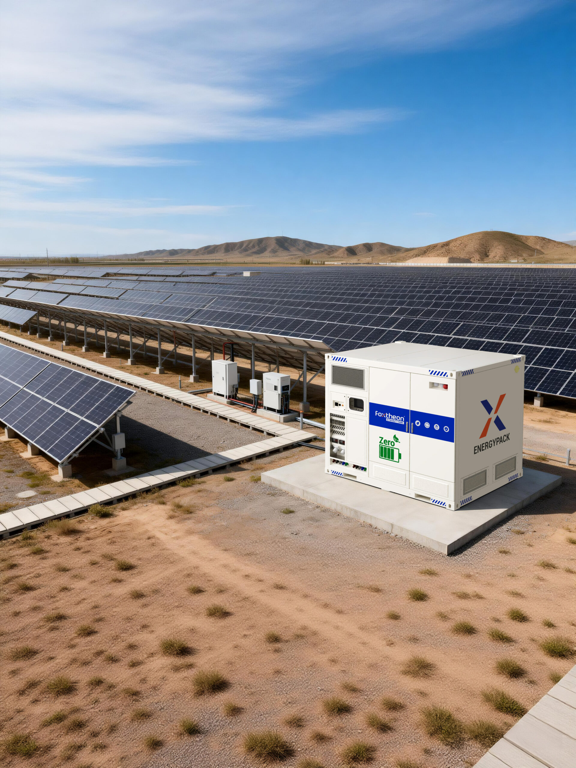
Modern power infrastructure demands continuous, high-fidelity electrical output while incorporating renewable generation sources into high-demand industrial environments. For plant operators, mine managers, and microgrid EPC engineers, solar hybrid solutions represent the operational standard for bridging photovoltaic variability with steady-state baseline power. When engineered correctly, these architectures harmonize multi-source generation matrices—including solar photovoltaic arrays, electrochemical energy storage systems (BESS), and reciprocating internal combustion engine generator sets—without compromising electrical safety or dynamic load response.
Industrial facilities operating on weak or isolated distribution lines frequently encounter thermal, kinetic, and control challenges. System engineering teams like those at Foxtheon develop advanced integration platforms designed to treat renewable components not as intermittent auxiliary power, but as synchronous-capable grid elements. Achieving this level of operational performance requires an in-depth understanding of power conversion systems, bus topology configurations, semiconductor selections, and deterministic communication networks.
Topology Foundations: AC-Coupled vs. DC-Coupled Microgrid Design
The core configuration of industrial-scale hybrid setups dictates overall conversion efficiency, harmonic distortion, and control stability under transient loads. System designers must evaluate DC-coupled and AC-coupled architectures based on load profiles, facility footprints, and the distribution of existing generation equipment.
AC-Coupled Microgrid Architecture
In high-capacity utility and commercial configurations exceeding 1 MW, AC-coupled topologies serve as the prevailing standard. Photovoltaic strings feed into dedicated grid-tied solar string or central inverters, outputting directly to an AC bus at intermediate low voltage (400V–690V) or medium voltage (11kV–33kV) through step-up transformers.
- Decoupled Subsystem Sizing: Photovoltaic generation fields, battery storage units, and generator sets operate via independent power conversion stages. This allows EPCs to expand individual generation assets without redesigning the DC intermediate circuits.
- Direct Solar-to-Load Dispatch: During periods where diurnal production matches baseline industrial demand, energy flows directly from PV inverters to downstream motor control centers without intermediate electrochemical conversion steps, preserving round-trip energy yields.
- Redundancy Profiles: A hardware failure on an isolated battery inverter or PV inverter does not halt the balance of the AC bus, allowing surviving assets to maintain operational continuity.
DC-Coupled Microgrid Architecture
DC coupling routes photovoltaic arrays directly to a common DC bus via high-voltage Maximum Power Point Tracking (MPPT) charge controllers, integrating alongside the battery rack systems. A centralized bidirectional power conversion system (PCS) subsequently manages the interface between the DC bus and the plant AC distribution network.
- Conversion Stage Reduction: Energy routed from the PV field directly into the battery bank undergoes a single DC-DC conversion step, minimizing thermal losses typical of double-conversion cycles (DC-AC-DC).
- Clipping Energy Recapture: In regions with high solar irradiance, oversized solar arrays that would typically exceed the AC inverter capacity channel excess power directly into the battery chemistry, maximizing energy harvest per installed module area.
- Synchronous DC Charging: Eliminates phase-matching latency on the charging interface, simplifying control loops for facilities running centralized low-voltage configurations.
Harmonizing Solar Integration with Thermal Generation Assets
Integrating solar capacity alongside established reciprocating internal combustion engines (diesel or heavy fuel oil generator sets) requires sophisticated control theory. Existing generator fleets represent dependable synchronous capacity; the engineering priority is to optimize fuel burn, maintain optimum thermal efficiency, and minimize engine carbon buildup without compromising power reliability.
A primary mechanical consideration is the prevention of generator “wet stacking”—a condition occurring when diesel units run beneath their minimum loading thresholds (typically 30% to 40% of rated nameplate capacity) for extended durations. Unburnt fuel accumulates in the exhaust manifolds, accelerating wear on piston rings, injectors, and turbochargers. Modern solar hybrid solutions deploy advanced Energy Management Systems (EMS) that actively calculate spinning reserve requirements against instantaneous irradiance data.
The control framework introduces specific active power curtailment and storage dispatch commands to maintain reciprocating engines within their optimal specific fuel consumption (SFC) sweet spots, commonly between 70% and 85% of rated load:
- Dynamic Spinning Reserve Management: The BESS acts as a virtual spinning reserve. If a heavy cloud band reduces solar array production across a multi-megawatt field within seconds, the battery PCS injects instantaneous active power (sub-20 millisecond response time). This eliminates the requirement to keep surplus diesel assets idling purely for contingency reserve.
- Droop and Isochronous Control Modes: In grid-isolated operations, the microgrid controller switches between frequency-droop (allocating load based on active power-frequency relationships) and isochronous modes. Advanced hybrid topologies configure grid-forming battery inverters to establish voltage and frequency baselines, allowing thermal units to operate at steady, high-efficiency baselines rather than chasing erratic high-frequency load steps.
- Reverse Power Protection: Directional power relays (ANSI device code 32) must be integrated into the control scheme. If PV generation exceeds total facility consumption while thermal generators are online, high-speed control feedback loops instantly throttle PV output or divert surplus energy into the BESS to prevent active power from back-feeding into the alternators, which would cause mechanical trip-outs.
Advanced Photovoltaic Technologies and Module Metallurgy
The primary generation layer of modern hybrid designs depends heavily on solar module semiconductor architecture. EPCs and system integrators must specify cell chemistry based on environmental degradation modes, localized thermal coefficients, and spectral response curves rather than superficial nameplate wattages.
TOPCon (Tunnel Oxide Passivated Contact)
N-type TOPCon modules have largely superseded older P-type PERC structures in industrial procurements. Featuring an ultra-thin silicon oxide tunnel layer combined with a passivated polycrystalline silicon contact layer, TOPCon technology significantly suppresses carrier recombination at the metallization interface.
- Temperature Coefficient Performance: Operates at an improved coefficient of -0.30%/°C (compared to PERC’s -0.35%/°C), providing substantially higher energy harvest in hot desert mining environments where cell operating temperatures exceed 65°C.
- Bifaciality Factor: TOPCon cells exhibit bifacial factors between 80% and 85%, absorbing reflected ground albedo onto the module rear side to boost overall generation density on high-reflectance soils or gravel surfaces.
- Degradation Immunity: The N-type substrate possesses zero susceptibility to Boron-Oxygen defect pairs, eliminating standard Light-Induced Degradation (LID) and drastically reducing Light- and Elevated Temperature-Induced Degradation (LeTID).
HJT (Heterojunction Technology)
Heterojunction modules combine thin layers of amorphous silicon on both sides of an N-type crystalline silicon wafer. This cross-material interface forms a superior passivation layer that delivers cell conversion efficiencies above 23.5%.
- Low Thermal Coefficient: Demonstrates a coefficient around -0.26%/°C, the highest temperature resilience among commercial silicon panels.
- High Bifaciality: Reaches rear-side generation efficiencies of up to 90%, optimal for dual-axis tracker systems or sites with high diffuse horizontal irradiance.
- Manufacturing Steps: HJT requires fewer processing steps than TOPCon but relies on low-temperature silver paste, necessitating meticulous vetting of module framing and junction box moisture-barrier integrity to prevent ingress-related degradation.
Energy Storage Systems and Conversion Architecture
Electrochemical storage serves as the dynamic balancing mechanism within solar hybrid solutions. For industrial duty cycles requiring multi-hour dispatch alongside rapid sub-second frequency regulation, Lithium Iron Phosphate (LiFePO4 / LFP) remains the primary chemistry due to thermal runaway resistance and long cyclic lifespans.
System architects must coordinate the thermodynamic and mechanical packaging of the battery racks with power conversion equipment. As demonstrated in industrial deployments by Foxtheon, thermal uniformity across battery modules is paramount. Liquid-cooling systems utilizing ethylene glycol-water loops maintain internal cell temperatures within a strict ±2°C gradient across a containerized 20-foot enclosure, preventing localized cell aging and preserving systemic state-of-charge (SoC) balance.
From an electrical perspective, modern conversion infrastructure prioritizes two central operational domains:
- Grid-Forming (GFM) Inverters: Unlike traditional grid-following systems that require an external voltage and angle reference from a generator alternator or utility line, GFM inverters function as virtual synchronous machines. Employing droop control algorithms or virtual synchronous generator (VSG) firmware, they deliver instantaneous synthetic inertia to the microgrid, dampening rate-of-change-of-frequency (RoCoF) events caused by sudden industrial motor starts.
- C-Rate Optimization: System sizing balances continuous thermal capacity with high discharge bursts. Standard industrial hybrid duty cycles balance 0.5C storage configurations (two-hour complete discharge profile for energy shifting) with brief 1C to 2C surge envelopes to absorb immediate inductive loads without triggering brownouts on isolated medium-voltage networks.
B2B Procurement and Engineering Evaluation Protocols
When engineering procurement teams evaluate components for high-capacity hybrid projects, standard datasheets are insufficient. Due diligence requires an examination of compliance certificates, quality assurance testing procedures, and hardware-software communication interoperability.
The matrix below outlines key verification points during the vendor qualification phase:
| Hardware Subsystem | Governing Standard | Key Technical Parameter to Validate |
|---|---|---|
| Photovoltaic Modules | IEC 61215 / IEC 61730 | Extended PID (Potential-Induced Degradation) testing duration (96h+ at 85°C/85% RH); rear encapsulation cross-linking density. |
| Power Conversion System | IEEE 1547 / UL 1741-SB | Low-Voltage Ride-Through (LVRT) envelopes; reactive power injection under zero-voltage fault scenarios; total harmonic distortion (THD) < 3%. |
| Battery Energy Storage | UL 9540A / IEC 62619 | Large-scale thermal runaway propagation test data; cell balancing topology (active vs. passive); aerosol fire suppression actuation logic. |
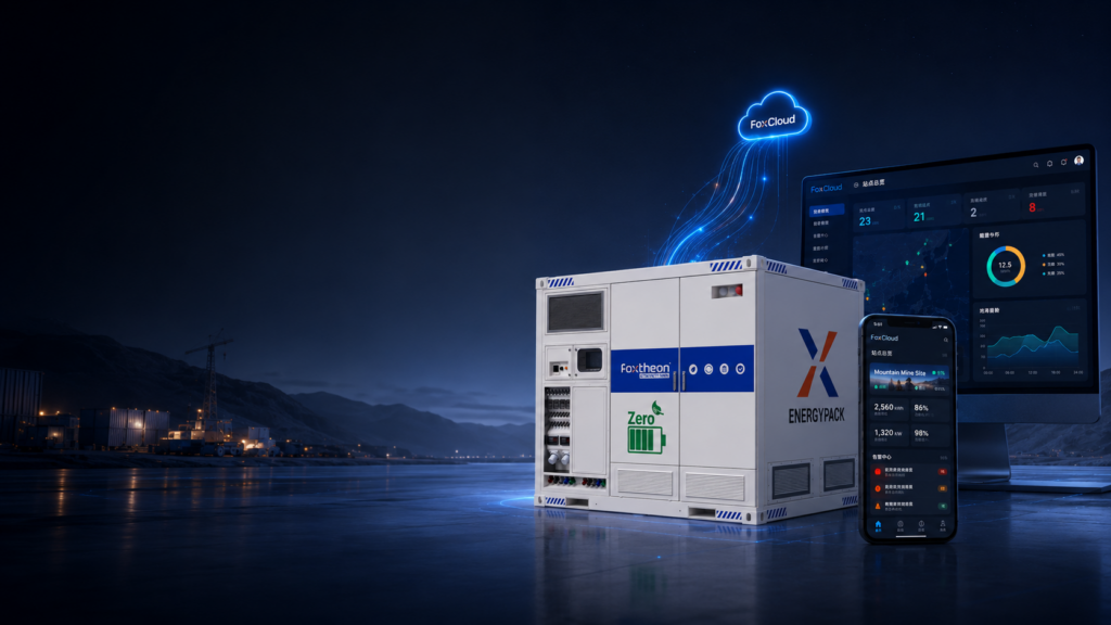
| Microgrid Controller / EMS | IEC 61850 / Modbus TCP | Control loop deterministic update rate (<100ms for load dispatch, <20ms for synthetic inertia); cyber-hardened communication isolation. |
A rigorous Factory Acceptance Test (FAT) protocol must precede site shipment. FAT parameters must encompass complete hardware-in-the-loop (HIL) simulations verifying that the programmable logic controllers (PLCs) handle abrupt operational transitions: islanding sequences, instantaneous load rejections, and black-start coordination between thermal engines and storage assets.
Industrial Use Cases and Deployment Environments
Deployment profiles for high-uptime solar hybrid solutions extend across multiple challenging continuous-duty sectors:
Remote Mineral Extraction and Processing
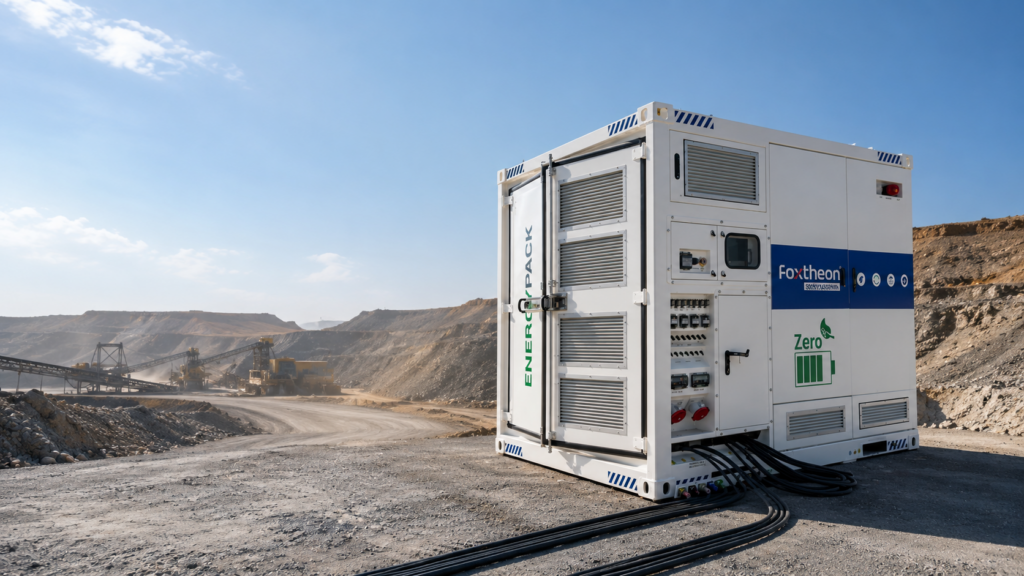
Mining operations require steady power to run ball mills, flotation circuits, and heavy haulage infrastructure. Sites operate on isolated island networks where power interruptions lead to settling tanks freezing or mechanical equipment blockages. Integrating high-yield PV modules, robust liquid-cooled energy storage, and dynamic control software permits mines to dramatically lower daily diesel consumption while maintaining steady bus frequencies under severe inductive switching cycles.
Weak-Grid Manufacturing and Industrial Parks
Facilities positioned at the terminal ends of utility feeder lines regularly deal with voltage sags, power factor penalties, and rotational shedding. By deploying behind-the-meter solar hybrid solutions, manufacturing plants utilize PV-generated energy during peak production windows, employ the battery systems for power factor correction and peak shaving, and synchronize auxiliary generation assets smoothly whenever utility lines fail completely.
Island Grids and Desalination Infrastructure
Municipal water extraction via reverse osmosis processes introduces significant energy loads with zero tolerance for power quality fluctuations. Pressure changes caused by electrical transients can rupture delicate filtration membranes. Hybrid power stations leverage the instantaneous response of high-speed battery conversion platforms to buffer photovoltaic intermittency, ensuring constant hydraulic pressure across membrane trains while prioritizing solar electricity consumption.
Frequently Asked Questions
Q1: How do modern hybrid setups prevent thermal generators from running beneath minimum load limits?
A1: The microgrid controller continuously monitors total load demand, PV production, and battery status. If solar output spikes to a point where internal combustion engines would drop below their 30%–40% minimum load threshold, the controller automatically modulates the solar inverters’ active power setpoints or redirects the surplus solar capacity into the battery bank. This mechanism maintains baseline engine loading, preventing wet stacking and unburned fuel accumulation.
Q2: What separates grid-forming inverters from conventional grid-following inverters in hybrid applications?
A2: Grid-following inverters monitor external voltage and frequency waveforms provided by an existing grid or thermal alternator, adjusting their current output to match that reference. Grid-forming inverters establish the voltage amplitude and frequency setpoints directly on the bus, acting as voltage sources. Utilizing internal droop-control programming and virtual synchronous algorithms, grid-forming units allow high-renewable penetration systems to run stably even when baseline synchronous machines are offline.
Q3: Why is N-type TOPCon or HJT preferred over standard PERC cells in industrial hybrid designs?
A3: N-type crystalline architectures (TOPCon and HJT) possess lower temperature coefficients, meaning their power output degrades at a slower rate when module temperatures rise under heavy irradiance. They also exhibit higher bifaciality factors (up to 85%–90%) and complete immunity to standard Boron-Oxygen Light-Induced Degradation (LID), delivering superior cumulative lifetime energy per square meter of array area.
Q4: How do control systems manage instantaneous cloud transients without dropping industrial motor loads?
A4: During an abrupt drop in solar irradiance, the primary control layer relies on the ultra-low latency response of the battery Power Conversion System (PCS). Rather than waiting for mechanical thermal generators to ramp their throttles—which can require several seconds—the battery inverters deliver active power within milliseconds via high-speed digital signal processors, mitigating transient frequency drops and keeping the bus stable.
Q5: What interface standards ensure seamless communication across multi-vendor equipment in a hybrid plant?
A5: Enterprise-grade industrial systems utilize deterministic industrial protocols, primarily Modbus TCP/IP, DNP3, and IEC 61850 over optical Ethernet rings. Standardizing communications ensures that the Energy Management System (EMS) polls data points—including PV string performance, battery pack temperatures, and alternator excitation parameters—with deterministic timing, avoiding the data packet collisions that undermine high-speed microgrid control.
Engineering Inquiries and Technical System Design
Specifying a utility-grade or industrial power system requires rigorous electrical modeling, dynamic stability studies, and hardware matching tailored to site-specific environmental conditions. For project development teams, EPCs, and facility directors structuring technical requests for proposal, Foxtheon provides engineering consultancy, load profile analysis, and integration blueprints for high-capacity applications.
Forward your single-line diagrams (SLD), site coordinates, baseline 15-minute interval load profiles, and existing thermal generation datasheets directly to our technical integration team:
Engineering Department: https://www.foxtheon.com/
Technical Inquiries: Contact an Applications Engineer for microgrid modeling, grid-forming battery topologies, and complete power integration documentation.